What Design Principles Govern Steel Sheet Pile Retaining Structures?
When a retaining structure fails, it almost never fails at random — it fails because one design principle was ignored.
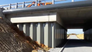
A steel sheet pile retaining structure is designed around four checks: balancing active and passive earth pressures, achieving adequate embedment depth, selecting a section with sufficient modulus, and adding anchors or props when cantilever action alone is not enough.
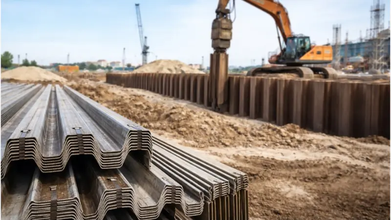
I have spent years supplying steel sheet pile retaining structures from our factory in Liaocheng to contractors across the Middle East, Australia, and Africa, and I can tell you that the drawings I receive from customers are getting more sophisticated every year. Still, the same handful of principles decides whether a wall stands for thirty years or leans after the first monsoon season. In this article I want to walk you through those principles the way I explain them to procurement engineers who buy from us — not as textbook theory, but as the practical logic behind every quotation we issue.
How Do Earth Pressures Shape the Design of the Wall?
Every retaining wall is a battle between the soil pushing it over and the soil in front resisting that push.
The wall must resist active pressure from the retained soil while mobilizing passive pressure in the embedment soil. Add water pressure, surcharge loads, and a factor of safety, and you have the complete lateral loading picture.
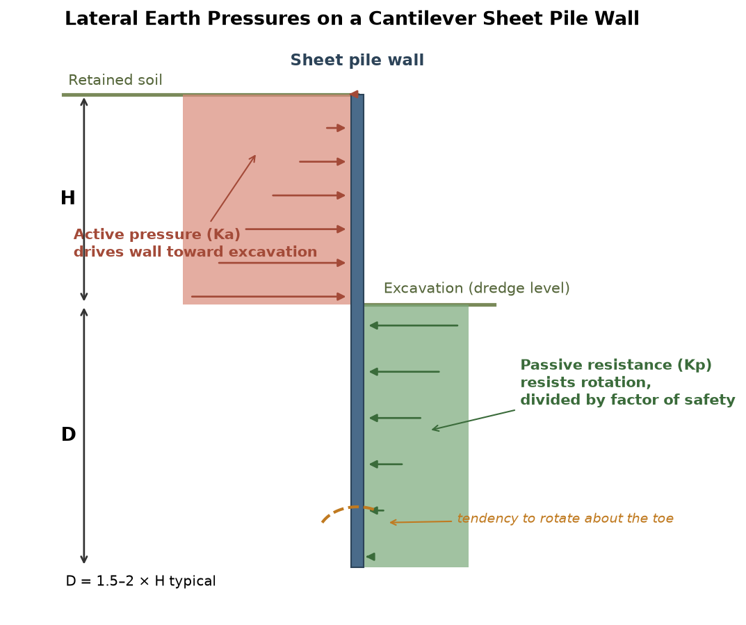
The starting point of any design is the lateral earth pressure diagram. The soil behind the wall pushes with active pressure — the minimum stress state that develops as the wall is allowed to move slightly outward. The soil in front of the wall resists with passive pressure — the maximum stress state, mobilized only when the wall presses hard into it. Between these two states, the wall finds equilibrium, and the designer’s job is to make sure that equilibrium holds with margin to spare. The classical earth pressure coefficients Ka and Kp come from the soil’s friction angle, and a five-degree error in that assumption can swing the required embedment by a meter or more.
What Else Loads the Wall Besides Soil?
Soil alone is rarely the whole story, and this is where I see the most costly omissions in customer drawings:
| Load Source | Typical Magnitude | Design Treatment |
|---|---|---|
| Active soil pressure | 25–45% of vertical stress (Ka ≈ 0.25–0.45) | Full design load over retained height |
| Passive resistance | 2–4× active pressure (Kp ≈ 2–4) | Divided by partial factor, usually 1.4–2.0 |
| Hydrostatic pressure | 10 kN/m² per meter of head | Full head if no drainage, reduced if weep paths exist |
| Surcharge (cranes, spoil, traffic) | 10–20 kN/m² or more | Added uniformly behind the wall |
| Differential water level | Large during rapid drawdown | Critical in tidal and river works |
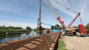
Water deserves special mention. In our marine and riverbank projects in Iraq and Australia, the difference between high and low tide can add a net pressure component larger than the soil itself. That is why we always ask customers about water levels before recommending a section — the same interlocked sheet pile wall that works at a drainable site may be badly undersized where full hydrostatic head applies. Good drainage design, relief weeps, and granular backfill reduce the load; ignoring them inflates it. When I review a tender, the first thing I check is whether the pressure diagram includes realistic water levels, because a wall designed for the wrong diagram is a wall designed for the wrong project.
How Deep Should the Wall Be Embedded?
The visible wall is only half the structure — the hidden half does the work.
Embedment depth is set by the required passive resistance below dredge or excavation level. Cantilever walls typically embed 1.5–2 times the exposed height; anchored walls can work with significantly less penetration.
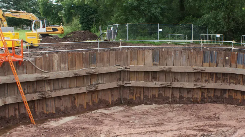
Embedment is the principle that surprises new buyers most. A six-meter exposed wall commonly needs six to nine additional meters buried in the ground, and clients sometimes ask me why we quote pile lengths that look “too long.” The answer is that the embedded portion is a lever: passive soil pressure acting on it creates the fixing moment that keeps the whole temporary or permanent wall upright.
Cantilever or Anchored — How Does That Change the Depth?
The two classical analysis methods produce different answers:
| Wall Type | Analysis Method | Typical Embedment Ratio | Best Application |
|---|---|---|---|
| Cantilever (free earth) | Moment balance about the toe | 1.5–2.0 × exposed height | Low walls, 3–5 m retained |
| Cantilever (fixed earth) | Toe fixity + bending check | Slightly deeper, less bending | Stiffer walls without anchors |
| Singly anchored | Free earth support | 0.7–1.2 × exposed height | Quay walls, most port works |
| Braced excavation | Empirical apparent pressure diagrams | Determined by strut layout | Basement and metro works |
On our cofferdam projects, we supply exactly to the depth the designer calculated — there is no benefit to us in overselling length, and no excuse for underselling it. What I do insist on is that the soil parameters used for passive resistance are conservative. Soft alluvial soil, common in delta regions where many of our customers build, may deliver only a fraction of the passive pressure assumed from generic tables. In those cases I recommend either deeper embedment or moving to an anchored scheme. A wall that mobilizes passive pressure in competent soil is efficient; one that relies on suspect soil is a gamble. When in doubt, a modest increase in driving length costs far less than remedial works after a wall has moved, and this reasoning applies equally to cofferdam and deep excavation walls.
One more subtlety: embedment is not only about overturning. The toe must also resist vertical load transfer where the wall carries surcharge, and it must reach a stratum where seepage paths around the toe are long enough to prevent piping in granular soils. On a river project in Bangladesh, the designer added just one meter of penetration after a flow-net check showed boiling risk at the excavation base — a cheap change on paper that prevented a very expensive underwater failure. Every one of these checks rides on the same number, the embedment depth, which is why I treat it as the single most important line on a quotation.
How Do You Choose the Right Section and Steel Grade?
Once the loads and depths are fixed, the pile must carry the bending moment.
The design bending moment, divided by the allowable steel stress, gives the required section modulus. Corrosion allowance and steel grade — S355GP, Q355, or higher — complete the selection.
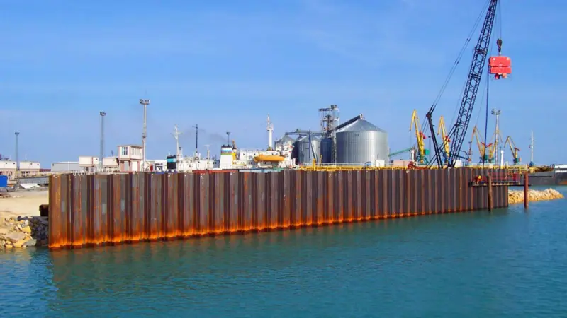
Section selection is where structural mechanics meets commercial reality. The maximum bending moment from the pressure diagram, divided by the yield strength of the steel, gives the minimum required section modulus — and then we round up to the nearest real product. A factor of safety applied to soil resistance and load combinations keeps the check honest under the worst credible conditions. This is the same logic behind the structural strength checks that every serious designer applies.
Which Factors Push the Section Up or Down?
| Factor | Effect on Required Section | Practical Note |
|---|---|---|
| Higher steel grade (S355 vs S270) | Reduces modulus need ~25% | Often cheaper than a heavier section |
| Anchors or props | Cuts design moment sharply | Cantilever walls need 2–3× the section |
| Corrosion allowance | Adds 1–2 mm per face over service life | Aggressive soils and marine splash zones demand more |
| Interlock reduction | ~10–15% modulus reduction at crimped corners | Depends on driving method and pile type |
| Reuse cycles | Straightening losses accumulate | Inspect before each reuse campaign |
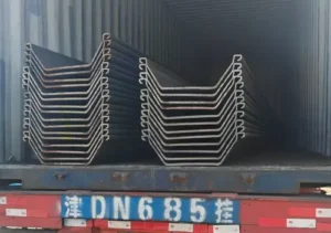
I always tell customers to look at steel grades before jumping to a heavier section: upgrading from S270 to S355 steel frequently costs less per square meter than the next section up, and our mill can roll both from the same coil stock. Corrosion is the other silent variable. A wall in a marine splash zone loses steel every year, and the design must either add sacrificial thickness, apply coatings, or plan for corrosion protection measures. In hot climates like the Gulf, where our Middle East customers work, the combination of warm seawater and alternating wetting is punishing, so I recommend that they never design on nominal thickness alone. The section you buy on paper should be the section that still has margin after twenty-five years in the ground, not the one that just passes the moment check on day one. Our SGS pre-shipment inspection verifies thickness, yield, and interlock fit so that the delivered product matches the design assumption — because a design principle only holds if the steel in the ground is the steel in the calculation.
When Should a Wall Be Anchored or Propped Instead of Cantilevered?
Past a certain height, no sheet pile section can do the job alone — the wall needs help.
Above roughly 4–5 meters of retained height, cantilever walls become uneconomical. Tied anchors, deadman systems, or internal bracing shorten the moment arm and cut the required section dramatically.
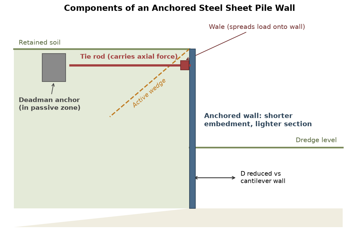
The choice between a cantilever wall and an anchored wall is fundamentally an economic one, governed by how bending moment distributes in each system. A cantilever must resist the full overturning moment at its point of fixity below grade, which means the moment — and therefore the required section modulus — grows roughly with the cube of the retained height. An anchored wall converts that same problem into an axial tie force carried by a soil anchor system, a wale, and a deadman or grouted anchor block behind the active zone.
What Are the Anchoring Options and Their Trade-offs?
| System | How It Works | Advantages | Watch-outs |
|---|---|---|---|
| Tie rod + deadman | Steel rod to a buried concrete or pile anchor | Simple, inspectable, cheap | Needs space behind the wall |
| Grouted ground anchors | Post-tensioned tendon into stable strata | No obstruction, high capacity | Specialist contractor required |
| Internal bracing (struts) | Steel frames across the excavation | Very stiff, controls movement | Obstructs excavation operations |
| Buttress / counterfort | Concrete ribs on the back of the wall | Reduces effective span | Permanent works only |
For port and quay projects, the tie-rod solution remains the workhorse because it is inspectable over the wall’s life and uses hardware any contractor understands. For deep urban basements — the metro and underground work our customers do in dense cities — internal bracing wins because movement control is paramount and the excavation is narrow anyway. What matters from my side of the supply chain is that the anchoring decision is made before sections are ordered: an anchored scheme typically lets me quote a one-or-two-weight-class lighter pile, and that saving frequently pays for the entire anchor hardware. I also remind designers that anchor loads concentrate at the wale, so connection details deserve real engineering attention, not last-minute site improvisation. Movement is the final check: an anchored wall stretched between two soil masses still deflects, and adjacent structures tolerate only so much. Realistic stiffness estimates, staged excavation sequencing, and monitoring points keep that movement honest.
I encourage every customer to instrument the first walls of a campaign. Simple survey targets along the wall head, read daily during excavation, cost almost nothing and confirm the design assumptions in real time. On one Australian flood pump station, a movement reading of 25 millimeters in the first excavation stage prompted the contractor to install an extra prop row before stage two — and the wall finished well within tolerance. That is what design principles look like on the ground: not a single dramatic decision, but a series of small verifications that keep the structure tracking the calculation.
My Take on How These Principles Fit Together
From my desk at the factory, the four principles are not independent checkboxes — they form a loop. The pressure diagram defines the moment; the moment defines the section; the section and height decide whether anchors pay for themselves; and the anchor scheme feeds back into the pressure diagram by stiffening the wall. The most successful projects I supply are the ones where the contractor, the designer, and the supplier talk early, while changes still cost nothing. When a customer sends me their soil report before finalizing the section, I can often suggest a grade or anchor tweak that trims real money off the package — and because we ship wholesale to general contractors, distributors, and civil engineering firms, those savings scale across a whole project, not just one truckload.
Conclusion
Balance the pressures, embed deep enough, size the section with margin, and anchor when economics demand it — master these four principles and your sheet pile wall will outlast the project around it.