How Do You Perform Numerical Analysis and Load Calculation for Steel Sheet Piles?
One wrong number can sink a wall. I have watched a missed surcharge load force a contractor in the Gulf to redo three weeks of excavation work. Get the loads right first.
Numerical analysis for steel sheet piles means converting soil, water, and surcharge loads into a bending moment, a deflection, and an embedment depth. I start with hand calculations for lateral earth pressure, then use finite element software to check deflection and safety before I confirm any pile order.
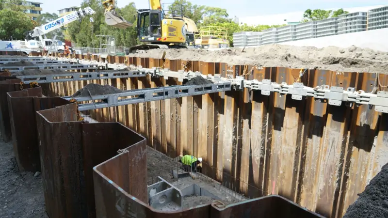
Most buyers I talk to only ask about price per ton. That is understandable, but the price conversation only makes sense after the calculation conversation. A wall that is sized correctly can use a lighter section. A wall that is sized by guesswork either wastes steel or fails in service. In this article, I will walk you through the exact workflow I use when customers send me their project drawings. I will cover the loads you must define, the hand calculation method, when to move to a numerical model, and how I validate the results before our factory in Liaocheng cuts a single pile.
What Loads Must You Define Before Any Steel Sheet Pile Calculation?
Skipping a load case is the fastest way to an unsafe wall. I always build a complete load list before I touch any formula or software.
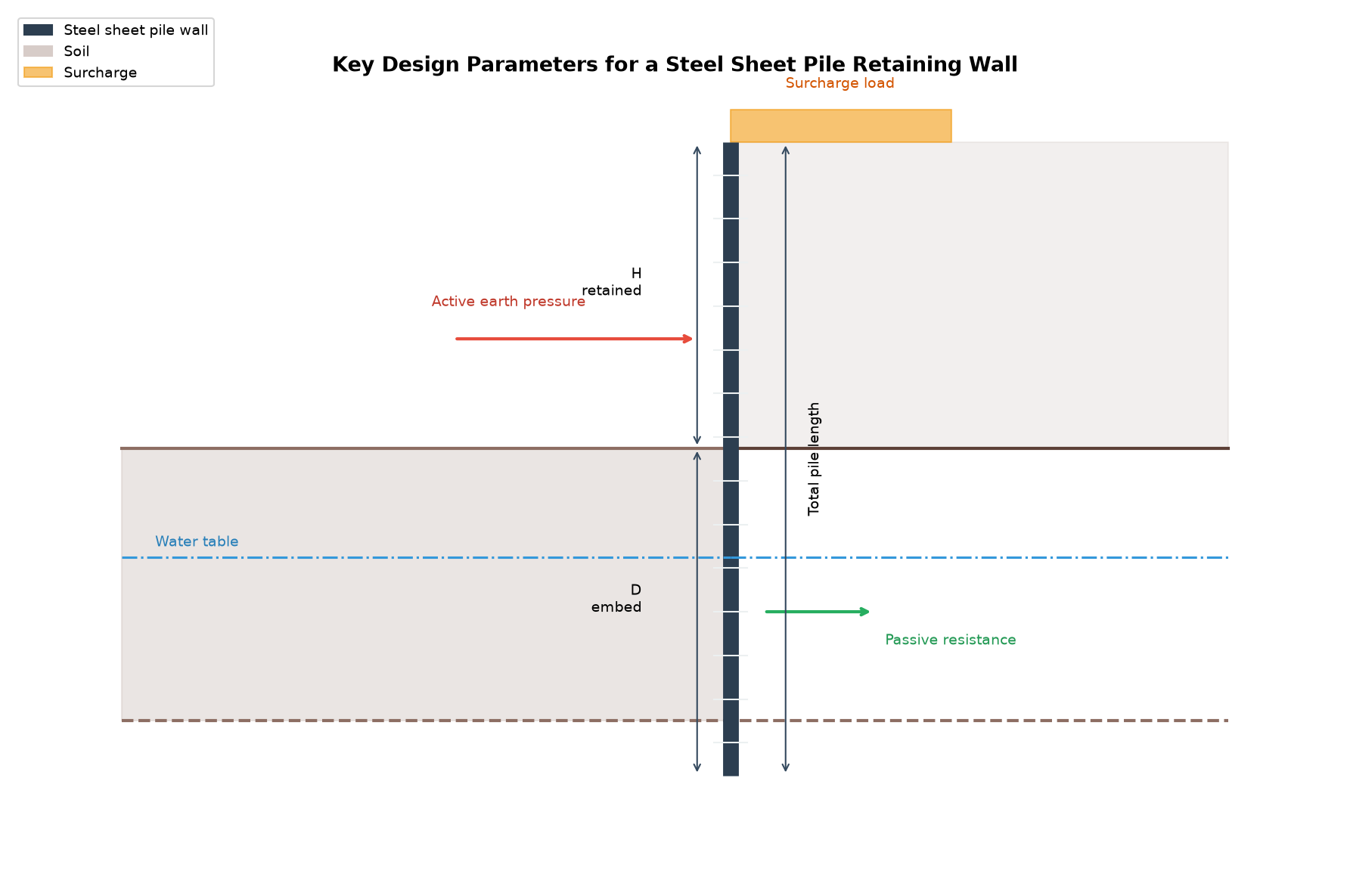
Before any calculation, you must define five load groups: lateral earth pressure from retained soil, hydrostatic water pressure, surcharge loads behind the wall, anchor or strut forces, and accidental loads such as impact or seismic action. Missing even one group will distort the bending moment and the required embedment depth.
Breaking Down Each Load Case
Let me go through these groups one by one, because each one behaves differently in the numbers.
Earth pressure is the main event. The soil behind the wall pushes with active pressure, and the soil in front resists with passive pressure. The ratio between them depends on the soil friction angle, the wall friction, and how the wall moves. This is pure soil mechanics, and it is the part of the calculation that deserves the most care. On many of the projects we ship to in the Middle East, the retained soil is loose sand, so the active pressure coefficient is high and the passive resistance is low. That combination drives deep embedment.
Water pressure is the second major force. If the water level differs on the two sides of the wall, the net pressure can add a huge bending moment. I have seen cases where water contributed almost half of the total moment. In coastal work, you also have to think about tide cycles and the possibility of a sudden drawdown after a storm. Lateral earth pressure theory handles soil and water together, but you must model the water tables separately. Water control is exactly where cofferdam projects live, and I explained the full picture in our guide on steel sheet piles for cofferdams and deep excavations.
Surcharge loads come from anything standing near the wall: cranes, material stockpiles, temporary roads, or adjacent buildings. A common rule is to include at least 10 to 20 kPa of uniform surcharge even on a “clean” site, because sites are never really clean.
The table below summarizes the load groups I check on every project.
| Load group | Where it comes from | Typical range | My rule of thumb |
|---|---|---|---|
| Active earth pressure | Retained soil behind the wall | 20–80 kPa at typical depths | Use conservative friction angle if lab data is thin |
| Passive resistance | Soil in front of embedded toe | Highly depth-dependent | Reduce by 25–50% for wall friction uncertainty |
| Hydrostatic pressure | Differential water levels | 10 kPa per meter of head difference | Never model both sides at the same level unless proven |
| Surcharge | Cranes, stockpiles, roads, buildings | 10–50 kPa uniform or line loads | Always include a minimum 10 kPa even on empty sites |
| Accidental loads | Impact, seismic, mooring forces | Project-specific | Treat separately with a reduced factor of safety |
One more thing I learned the hard way: temporary loads are real loads. During the driving stage, before any struts are placed, the wall sees a completely different load path than it will in service. Your calculation must cover every construction stage, not just the final one.
How Do You Hand-Calculate Earth Pressure and Bending Moments?
Software is convenient, but if you cannot do the hand calculation, you cannot judge the software output. I never skip this step.
The standard hand method is the free-earth approach: compute active and passive pressure distributions, find the point where they balance, take moments to solve the embedment depth, then shear and moment diagrams give the maximum bending moment for section selection.
The Free-Earth and Blum Methods in Practice
The free-earth method treats the wall as a simply supported beam. The passive pressure in front is the support, the active pressure behind is the load. You increase the embedment depth until the moment balance works with an applied factor of safety, typically 1.5 to 2.0 on passive resistance. It is conservative, and that is exactly why I like it for first-pass sizing.
The Blum method goes one step further for cantilever walls. It assumes the wall rotates about a point below the excavation line, so there is a fixed-earth support at depth. This usually gives a shorter embedment but a higher maximum moment near the rotation point. When I compare the two methods for the same wall, Blum typically reduces the toe length by 15 to 25 percent, but it concentrates more moment in the pile.
Here is how the pressure coefficients work in practice. For a granular soil with a friction angle of 30 degrees, the active coefficient Ka is about 0.33 and the passive coefficient Kp is about 3.0, ignoring wall friction. That 1-to-9 ratio is the whole game: passive resistance is precious, so every meter of safe embedment buys a lot of capacity. For cohesive soil, you work with undrained shear strength instead, and short-term versus long-term behavior can flip the answer completely.
| Calculation step | Free-earth method | Blum method | Notes from my projects |
|---|---|---|---|
| Soil model | Rigid plastic (Rankine/Coulomb) | Rigid plastic, rotation point | Soft clays need special care in both |
| Embedment depth | Longer, direct moment balance | 15–25% shorter typically | Blum needs a check on toe fixity |
| Max moment location | Near excavation line | Below excavation line | Affects driving and handling stresses |
| Best use case | Anchored or strutted walls | Cantilever walls | I use free-earth for first estimates always |
| Safety factor | Applied on passive side | Applied on passive side | 1.5 for temporary, 2.0 for permanent work |
Once I have the maximum bending moment, section selection is straightforward. Divide the moment by the allowable steel stress to get the required section modulus, then pick a section from our catalog. This is also where steel grades matter: an S355 grade gives you about 35 percent more yield strength than an S275 in the same envelope. For buyers comparing quotes, always check that the quoted section modulus matches the calculation, not just the tonnage. I wrote a full guide on how to read and compare common steel grades used for steel sheet piles if you want the details.
When Should You Switch from Hand Calculations to Numerical Analysis?
Hand methods got our industry through a century of building. But some conditions simply demand a numerical model, and pretending otherwise is risky.
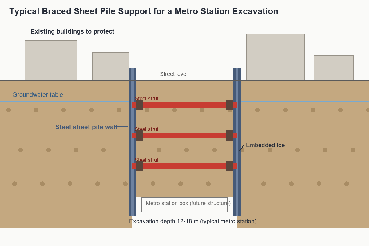
Switch to finite element numerical analysis when the wall is high or flexible, when soil stratification is layered or soft, when groundwater control is complex, when adjacent structures are sensitive to movement, or when staged construction changes the load path. For simple temporary works under 6 meters, hand calculations are usually enough.
What a Finite Element Model Adds
The finite element method models the wall and the soil as a continuum. Instead of assuming rigid plastic failure wedges, the software tracks how stress redistributes as you excavate stage by stage. This gives you three things a hand calculation cannot provide.
First, deflections. Hand methods give you moments, but moment does not equal movement. A wall can pass every strength check and still deflect enough to crack a neighboring building. FEM predicts the deflection profile, which is what neighbors and city inspectors actually care about.
Second, realistic soil-structure interaction. The wall is not perfectly rigid and the soil is not perfectly plastic. With a constitutive model such as hardening soil or a small-strain stiffness model, the analysis captures how the soil stiffens and softens under each construction stage. In layered ground, this matters enormously. When a customer sends me a borehole log with three or more alternating layers of sand, silt, and clay, I immediately recommend numerical analysis, and I also point them to our guide on how to select sheet piles based on soil conditions. Our solutions for challenging ground conditions page covers many of these situations.
Third, staged construction. Excavate, install strut one, excavate deeper, install strut two. Each stage changes the stress state. Hand methods only handle the critical final stage well. FEM handles all stages, which lets the contractor plan the exact sequence.
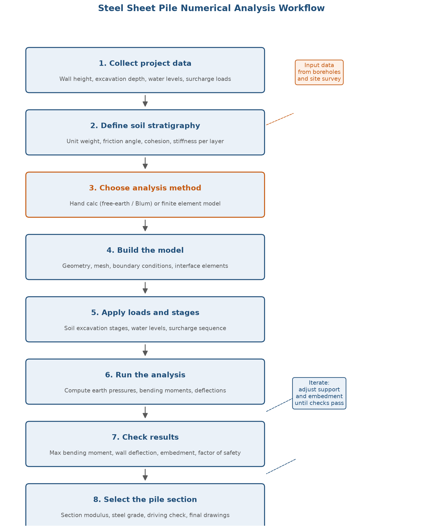
The workflow diagram above shows the full loop I follow: project data, soil parameters, method choice, model building, staged loading, analysis, checks, and finally section selection. Notice the iteration loop in the middle. Numerical analysis is not a one-shot calculation. I usually run the model two or three times, adjusting support stiffness and embedment until all checks pass with margin.
| Factor | Hand calculation | Finite element analysis | My decision rule |
|---|---|---|---|
| Wall height / cut depth | Up to ~6 m comfortably | No practical limit | Below 6 m, hand calc wins on speed |
| Soil profile | 1–2 idealized layers | Many layers, any behavior | 3+ layers or soft clay → FEM |
| Deflection prediction | Not available | Full profile | Adjacent structures → FEM |
| Groundwater complexity | Simplified net pressure | Full seepage and flow rules | Dewatering cases → FEM |
| Time and cost | Hours | Days including setup | Budget drives small projects |
| Output confidence | Conservative envelope | Behavior-based | Cross-check FEM against hand calc |
That last row is important. I never let FEM completely replace the hand calculation. I run both, and if the two answers diverge by more than about 20 percent, something is wrong with one of them. Usually the soil parameters need a second look.
How Do You Validate Numerical Results Before You Order Piles?
A model that looks beautiful on screen can still be wrong. Validation is what separates a real calculation from a screen saver.
Validate numerical results with three checks: compare against a hand calculation envelope, confirm soil parameters against published correlations and lab tests, and compare deflections with monitored case records of similar walls. Only after all three pass do I release the section for production.
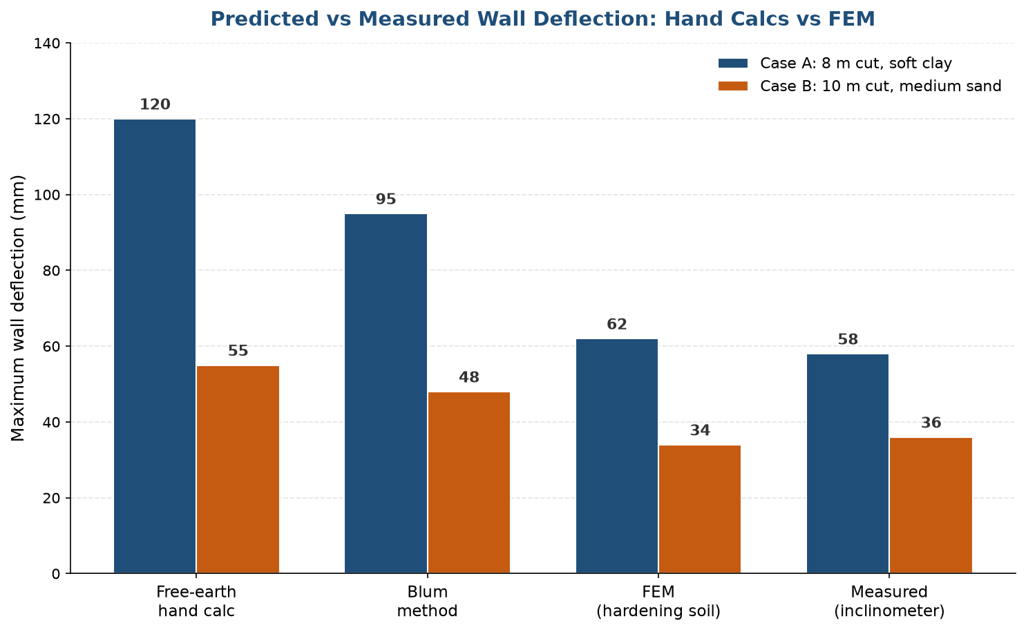
My Three-Layer Validation Routine
The chart above shows why validation matters. In Case A, an 8 meter cut in soft clay, the free-earth hand calculation predicted 120 millimeters of movement while the measured value was 58. The classical method was conservative by a factor of two, which is safe for strength but wasteful for steel. In Case B, a 10 meter cut in medium sand, the finite element model predicted 34 millimeters against 36 measured. That is engineering. But FEM only reached that accuracy because the input parameters came from real site investigation, not a textbook.
Layer one is the hand calculation cross-check. As I said, the free-earth result is my conservative envelope. If FEM predicts a lower moment than free-earth, fine, that is normal. If FEM predicts a higher moment, I investigate before believing it.
Layer two is parameter sanity. Soil stiffness values control FEM deflections more than almost anything else. I check every modulus against published correlations with friction angle or undrained shear strength. If the geotechnical report says one thing and the correlation says something very different, I call the engineer and ask questions. Garbage in, garbage out applies to soil models more than anywhere else.
Layer three is case record comparison. Published monitoring databases give measured deflection ratios for different wall types and soils. If my model predicts behavior far outside those records, I distrust the model. This is the same habit I bring from structural strength and load-bearing capacity reviews, where we compare calculated capacity against tested values.
| Validation check | What it catches | How I do it | Frequency |
|---|---|---|---|
| Hand calc envelope | Model errors, wrong load paths | Free-earth comparison | Every project |
| Parameter correlations | Bad soil stiffness inputs | Published correlations vs lab data | Every model |
| Case record range | Overconfident predictions | Published monitoring databases | FEM projects |
| Stage-by-stage review | Construction sequence errors | Print and read each stage output | Every FEM run |
| Sensitivity run | False precision | Vary key parameters ±20% | High-risk projects |
Only when all these checks pass do I send the final section recommendation to production. This discipline matters because the next step in the chain is physical: our mill bends the coil, our yard stacks the piles, and a vessel in Jebel Ali or Brisbane waits for a section that must perform exactly as calculated. There is no “update the software” option once steel is driven into the ground. For permanent structures, I also point customers to the difference between temporary vs permanent steel sheet pile structures, because design life and corrosion allowance change the calculation inputs as well.
If you want to see how these numbers turn into a finished structure, our article on the design principles of steel sheet pile retaining structures walks through the other side of the same process.
My Take
I will give you my honest opinion after years of quoting and shipping steel sheet piles worldwide. Most calculation problems I see are not math problems. They are data problems. Customers send me a one-line request with an excavation depth, and they expect a section name back. I cannot responsibly do that, and neither can any serious engineer. The projects that go smoothly, from Iraq to Australia, all started with the same thing: a proper borehole log, a real water table, and an honest surcharge assumption. If you bring me those three things, I can optimize your section and save you real money. If you bring me a depth and a deadline, I will quote you a heavier, safer section than you need, because I have no choice. The calculation is not a formality before procurement. It is the procurement decision itself, just written in the language of bending moments. Spend your money on site investigation before you spend it on steel. In my experience, every dollar spent on geotechnical data saves five in steel weight.
Conclusion
Define every load, hand-calculate the pressure balance, use numerical analysis for complex or sensitive walls, and validate everything before ordering. Numbers first, steel second. That is how I do it.