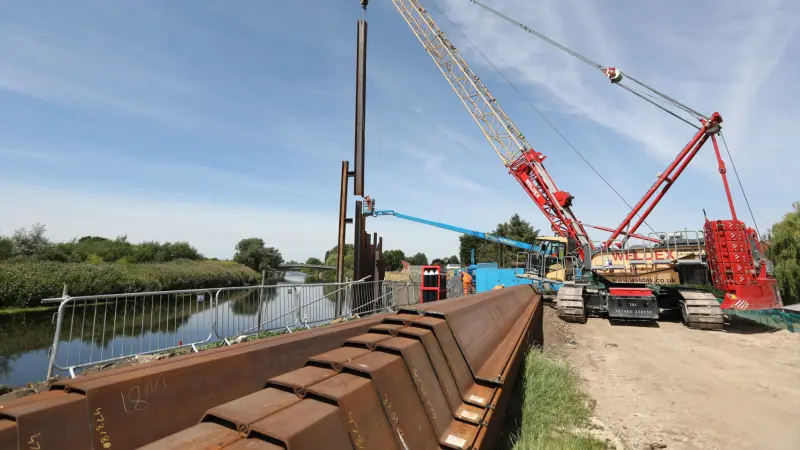
How Do Steel Sheet Piles Perform in Seismic and High-Water-Level Areas?
Floods and earthquakes push retaining walls to their limits. I have seen both ruin cheap walls in one season. Steel sheet piles survive both — if you design them right.
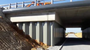
Steel sheet piles perform well in seismic and high-water-level areas because their interlocked walls act as flexible, ductile panels. They bend without brittle failure, resist water pressure with deep embedment, and can be combined with drainage, anchors, and corrosion protection for long service life.
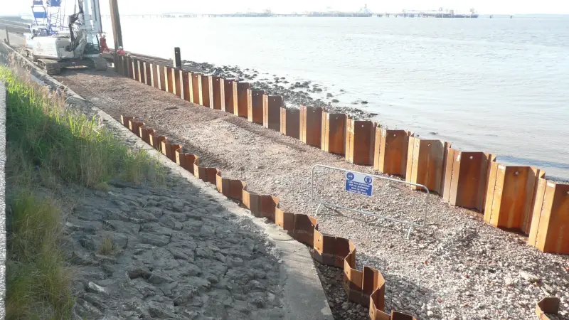
In my factory in Liaocheng, we ship piles to Iraq, Jordan, Pakistan, and other markets where rivers flood hard and the ground can shake. Buyers in these regions ask me the same questions again and again. So in this article, I will answer them one by one. I will cover seismic behavior, water pressure, steel grades, installation, corrosion, and real project lessons. Keep reading if your next site sits near a river or a fault line.
Why Do Earthquakes Put Extra Demands on Sheet Pile Walls?
An earthquake turns quiet soil into a moving, fluid mass. A rigid wall cracks. A steel sheet pile wall bends, and that is exactly why it survives.
During an earthquake, soil pressure on a sheet pile wall can rise far above its static value, and loose saturated sand may liquefy. Steel sheet piles handle this because steel is ductile: the wall can flex, redistribute load, and tolerate large permanent movement without collapsing.
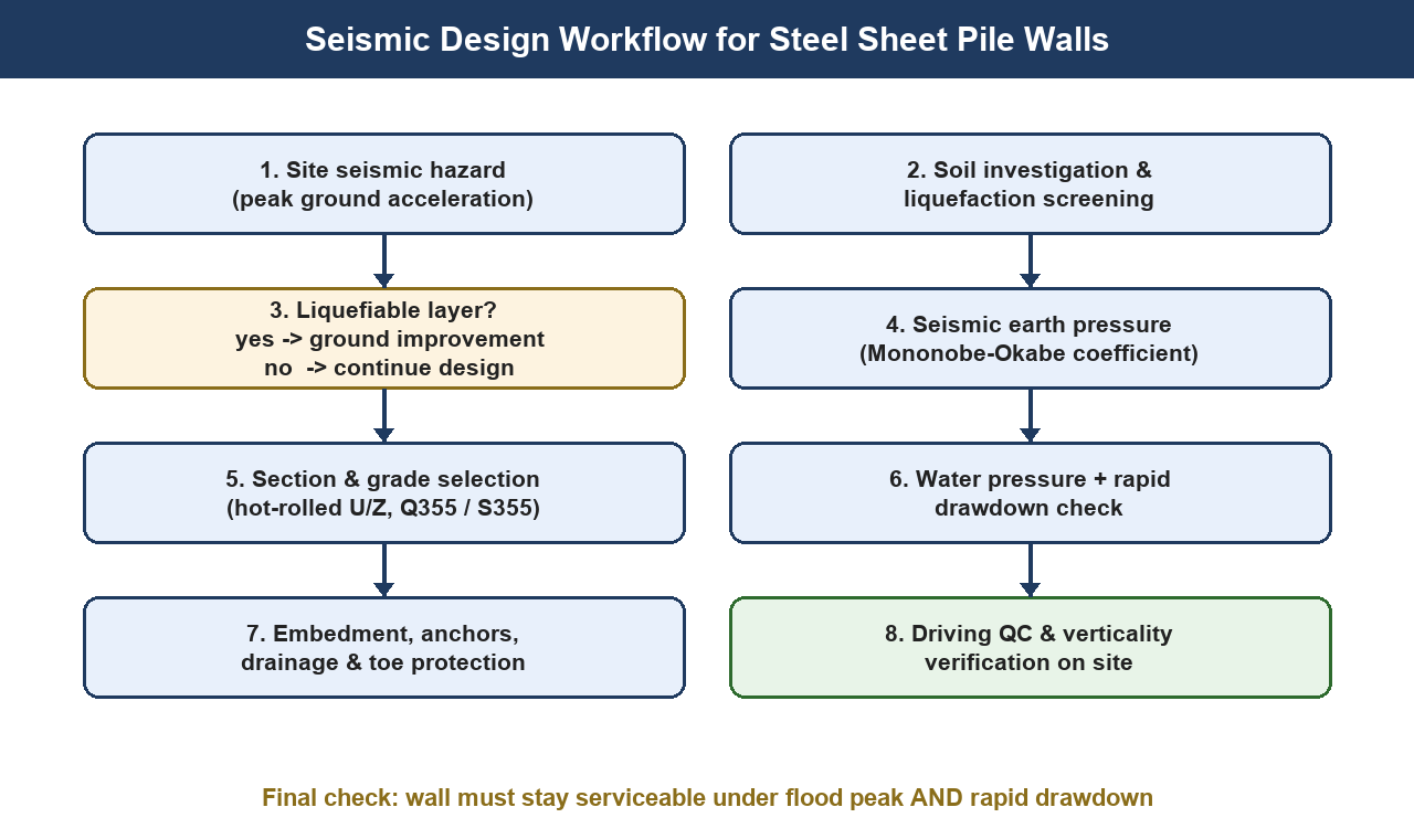
What actually happens to the wall during a quake?
Let me break the shaking into three effects I always check.
First, there is the inertial load. The soil behind the wall accelerates and pushes harder. The classic Mononobe-Okabe method adds a seismic coefficient to the normal earth pressure. In simple terms, the design pressure grows as the shaking grows.
Second, there is liquefaction. Loose, saturated sand loses its strength when shaken. It behaves like a heavy liquid. A wall designed for firm soil can suddenly face pressure from a fluid slurry on one side and softened support on the other. This is the failure mode I worry about most, and I screen every project for it with standard soil liquefaction criteria.
Third, there is the wall itself. Steel yields before it snaps. A concrete diaphragm wall under the same load may crack and lose integrity. A sheet pile wall may end up leaning 2 or 3 degrees after a big quake, but it still holds back the soil and the water. I call that a win.
Here is how I compare the main wall types for seismic sites:
| Wall type | Ductility | Seismic behavior | Typical failure mode |
|---|---|---|---|
| Steel sheet pile wall | High | Flexes, redistributes load | Permanent tilt, rarely collapse |
| Concrete diaphragm wall | Low | Rigid, attracts load | Cracking, joint opening |
| Gravity masonry wall | Very low | Brittle under shaking | Toppling, sliding out |
| Soldier pile and lagging | Medium | Lagging may spill soil | Local soil runs between piles |
The takeaway is simple. In a seismic zone, you want a wall that can move. Steel gives you that. For the design steps behind this, see our guide on the design principles of steel sheet pile retaining structures.
How Does a High Water Level Change the Design?
Water is heavier than most buyers think. A rising river does not just push on the wall — it changes the soil behind it too.
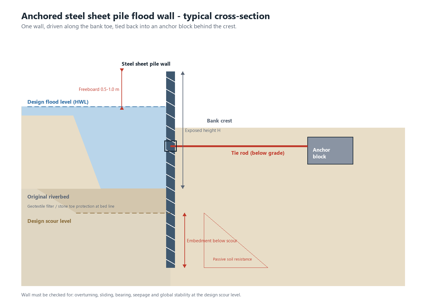
High water level increases lateral pressure on a sheet pile wall, reduces the effective weight of the soil, and weakens seepage stability at the toe. Designers respond with deeper embedment, thicker sections, drainage systems, and toe protection to keep the wall stable through the full flood cycle.
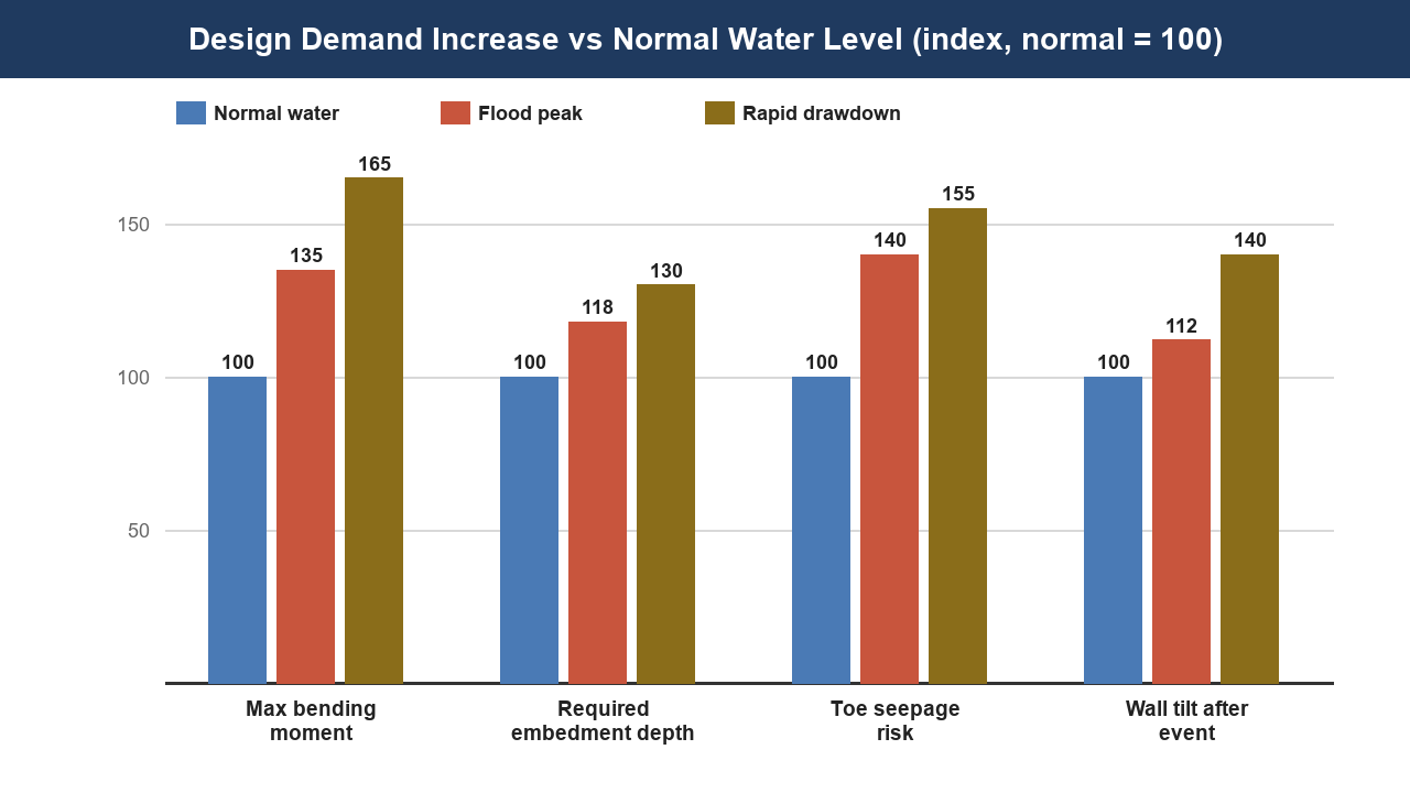
Why is rapid drawdown the worst case?
Many people design for the flood peak and forget the day after. That is a mistake.
When a flood peaks, water stands on both sides of the wall at similar levels. The pressures partly balance. The dangerous moment comes when the river drops fast. The water inside the soil behind the wall drains slowly. For a while, the river side is low but the soil side is still saturated and pushing hard. This condition is called rapid drawdown, and it creates the largest unbalanced pressure of the whole flood cycle.
I once reviewed a failed river wall in a Southeast Asian project. It stood fine through two floods. It failed during the drawdown after the third one, when the water level fell almost two meters in one night. The wall had no weep holes and no drainage layer. The trapped water pushed the toe out. A simple filter and drainage design would have saved it.
The fix list is not long:
| Design element | What it does | My rule of thumb |
|---|---|---|
| Deeper embedment | Resists pressure and piping at the toe | Add 15–25% penetration vs dry sites |
| Weep holes + geotextile | Relieves trapped water behind wall | Never skip on river walls |
| Tie rods or anchors | Cuts bending moment and toe demand | Use above high water, easy to inspect |
| Section upgrade | Handles higher bending moment | Check both flood peak and drawdown |
| Toe protection (rock) | Stops scour from undermining the wall | Place before driving, not after |
If you match the embedment and drainage to the real water range, a sheet pile wall will outlive the project around it. More details are in our article on riverbank and flood control solutions.
Which Steel Grades and Sections Suit These Conditions Best?
Not every pile section works everywhere. In seismic and high-water areas, I push buyers toward hot-rolled sections with real reserve capacity.
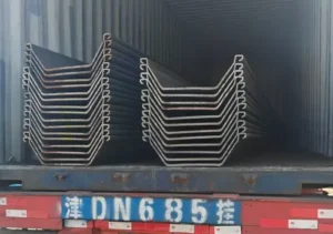
For seismic and high-water-level sites, I recommend hot-rolled U or Z sections in grades like Q355 or S355. Higher yield strength gives reserve against shock loads, and the thick interlocks of hot-rolled piles resist damage during driving and handle repeated loading far better than thin cold-formed panels.
How do I pick the grade and the section?
I start with three questions. How deep is the water? How loose is the soil? How strong is the shaking?
For water depth, the answer drives the bending moment. Every extra meter of retained water adds pressure over the full wetted height. A section that works for a 4 meter wall in dry ground may be undersized for the same wall holding 4 meters of water.
For soil, loose sand and soft silt both call for bigger sections and deeper toes. Our guide on selecting sheet piles by soil conditions covers the screening logic.
For shaking, the seismic coefficient raises the design pressure. I also look at fatigue. In seismic areas, the wall may see many moderate events over its life. Thick hot-rolled interlocks handle this cyclic loading much better than thin cold-formed locks. The interlock is the heart of the wall, so I never cheap out there. You can read more in our piece on interlock types and performance.
A quick comparison I use with buyers:
| Condition | Suggested grade | Suggested section family | Key check |
|---|---|---|---|
| Moderate quake, shallow water | Q235B / S275 | U type, medium modulus | Interlock strength |
| Strong quake or deep water | Q355B / S355 | Hot-rolled U or Z, high modulus | Bending + seismic combo |
| Liquefiable sand present | Q355B / S355 | Z type with crimped or welded interlocks | Liquefaction screening |
| Long-term marine/flood exposure | S355 or ASTM A690 | Hot-rolled, thicker flange | Corrosion allowance |
One more note from my factory floor. Cold-formed piles have their place in light, temporary works. But when a buyer tells me the site floods yearly or sits near a fault, I quote hot-rolled first. The price difference is small compared to the risk.
How Do You Install Sheet Piles in Liquefiable or Saturated Ground?
Good steel can still fail if it is driven badly. Soft, wet, or loose ground punishes every shortcut.
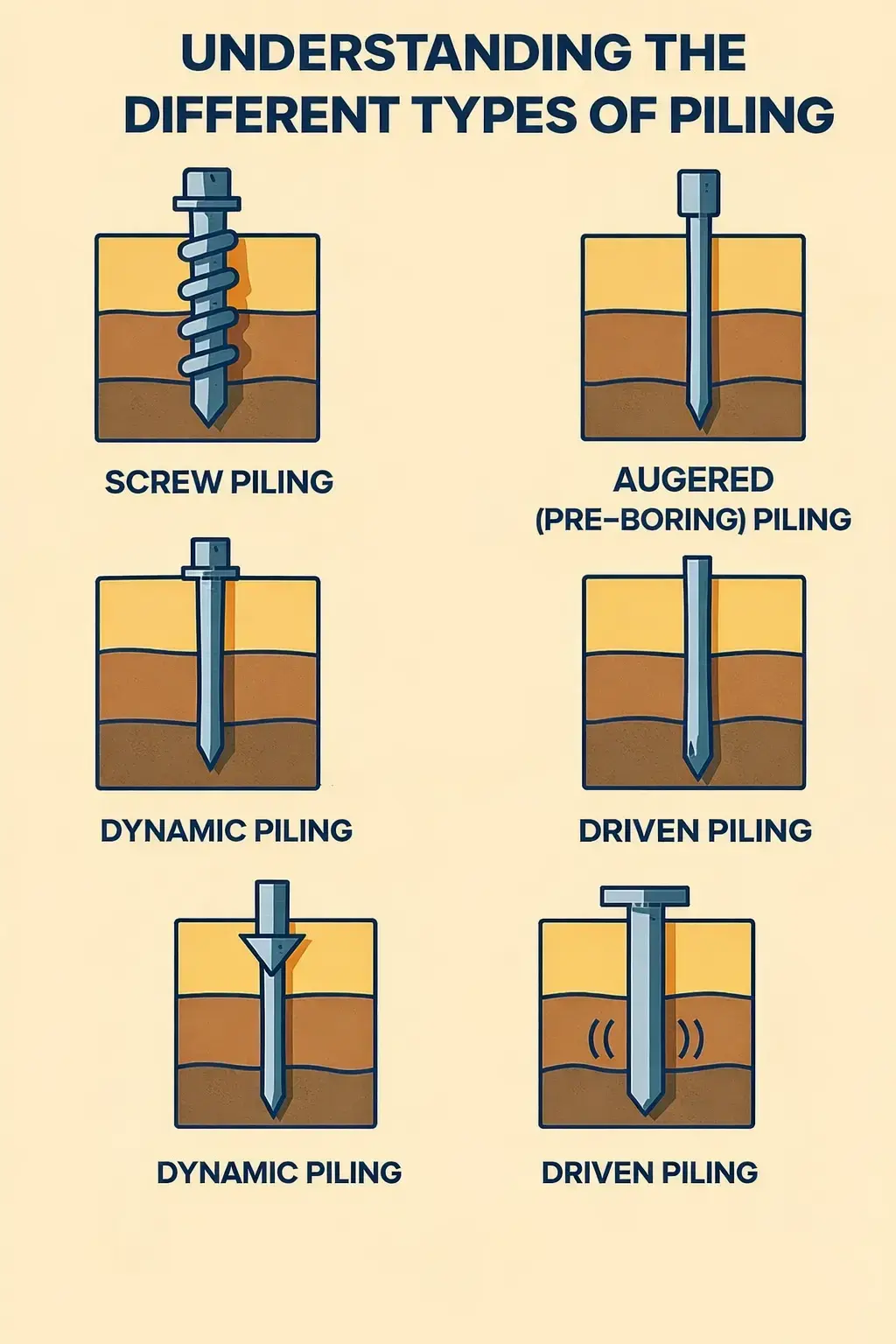
In saturated or liquefiable ground, install sheet piles with a vibratory hammer where possible, keep leads tight to control verticality, drive in pairs or panels, and watch for unexpected set or sudden drop. Add ground improvement in the loosest zones before driving, not after problems appear.
What should the crew watch for on site?
I visit client sites when I can, and the wet-ground failures I see follow the same patterns.
The first pattern is refusal followed by sudden drop. In loose saturated sand, the pile can hang on a dense layer, then punch through it fast. If the crew keeps full energy on the hammer, the pile runs out of line. I teach crews to reduce energy when the set changes and re-check the leader angle.
The second pattern is interlock damage. Driving a wall through dense layers with a light hammer takes too many blows. Heat and wear eat the interlocks. Use a hammer with enough energy to finish the drive in a reasonable blow count. Match the hammer to the soil, not to what is already on the yard.
The third pattern is pre-boring mistakes. In very dense sand or gravel lenses, pre-augering helps the pile start true. But if the bore is too wide, the soil support disappears and the pile wanders. Keep the pilot hole smaller than the pile width.
On liquefiable sites, I also support ground improvement before driving. Stone columns, compaction grouting, or simple vibratory densification can turn a risky sand layer into a decent one. The method choices are well summarized under ground improvement practice, and the cost is usually far below the cost of repairing a failed wall.
| Site condition | Recommended method | Key precaution |
|---|---|---|
| Loose saturated sand | Vibratory hammer | Watch sudden drop, re-check line |
| Soft silt / soft clay | Vibratory, then impact to set | Slow final set, check toe level |
| Sand with dense lenses | Impact with adequate energy | Pre-auger only where needed |
| Gravel or fill with obstructions | Impact + pre-drilling | Keep pilot hole tight |
| Liquefiable layer confirmed | Improve ground first | Verify densification before driving |
Verticality deserves its own mention. A wall that is driven out of plumb will show gaps and stress concentrations for its whole life. Our checklist for vertical accuracy during driving covers the practical controls.
What Corrosion and Durability Measures Do These Sites Need?
Water and shaking are not the only enemies. Time is the third one, and it works through rust.
In high-water-level areas, corrosion concentrates in the splash and low-water zones. Combine a corrosion allowance in the section, protective coatings, and cathodic protection for permanent works. For aggressive soils or salt water, a thicker hot-rolled section or a higher-grade steel often pays for itself within the design life.
The corrosion pattern in water is not uniform. The zone just above and below the average water line loses metal fastest. It gets wet and dry in cycles, with oxygen in plenty. Fully buried zones corrode much slower. So I do not spread the allowance evenly — I check where the wall will actually sit relative to the water range.
For permanent flood walls, my standard package looks like this: a section chosen with 1.5 to 2 mm of sacrificial thickness in the splash zone, a quality epoxy or polyurethane coating over the exposed height, and cathodic protection where the soil or water is aggressive. Where the water carries salt, we look at cathodic protection from day one, and where regulations allow, marine-grade steels such as ASTM A690 are worth a serious look.
For temporary works, I am honest with buyers. A cofferdam that stands for one or two seasons rarely needs coatings at all. Uncoated sections with a small allowance are the economic answer, and the piles return to our yard for reuse. The full reasoning, with zone loss rates, is in our article on corrosion resistance solutions.
| Exposure zone | Relative corrosion rate | Recommended measure |
|---|---|---|
| Above high water (atmospheric) | Low | Coating, optional |
| Splash / tidal zone | Highest | Coating + allowance, mandatory |
| Between tides, permanently wet | Medium | Coating or allowance |
| Below mudline (buried) | Low | Allowance only |
| Aggressive / saline soil | Medium to high | Coating + cathodic protection |
What Real Projects Teach Us About These Conditions?
Theory is fine, but I trust project stories more. Let me share the patterns from our export markets.
In flood-prone and seismic markets like Southeast Asia, the Middle East, and Pakistan, the successful sheet pile projects share three habits: honest ground investigation, deeper embedment than the minimum, and drainage design that matches the real water cycle. Projects that skip one of these pay for it within a few flood seasons.
Our case files repeat one story. A Southeast Asian riverbank project used hot-rolled U-type piles with a vibratory rig. The wall has held through several flood seasons because the contractor drove to the full design depth even where the top soil looked firm. Neighboring cheap walls, driven short, needed repairs.
In the Middle East, the challenge flips. Water is scarce, but when it comes, it comes violently. Wadi floods hit walls with debris loads and scour in hours. There I push deeper toe protection and rock berms more than bigger sections.
In Pakistan and other seismic markets, buyers often combine our piles with simple anchors. A tied wall has a much easier life during an earthquake than a pure cantilever. Anchors cut the moment demand and keep the tilt small.
My view from all of this is consistent. The steel is rarely the problem. The details — depth, drainage, interlock quality, and honest soil data — decide the outcome. I would rather quote a slightly heavier section with a proper drainage package than win a bid with a bare minimum wall that fails in year three. That is how we have kept long-term customers across four continents.
Conclusion
Steel sheet piles handle earthquakes and high water better than rigid walls because steel bends instead of breaking. Add honest design for water pressure, drainage, and corrosion, and the wall will outlast the project.