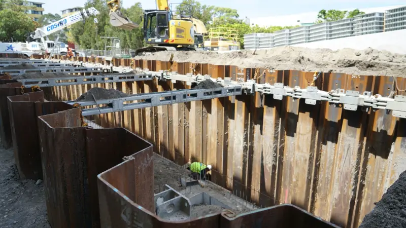
Every project starts with one number: the clear retained height. Get it wrong and the section, the pile length and the anchor design all drift with it.
Wall height sets the bending moment, and the moment sets the section modulus. Because the moment grows with the cube of the height, a 4 m cantilever wall needs roughly 1,000 to 2,100 cm³/m of steel, while an 8 m anchored wall needs 1,600 to 2,400 cm³/m plus an anchor.
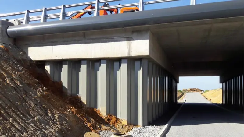
I have quoted walls from our mill in Liaocheng for fifteen years, and the pattern never changes. The height on the drawing decides the profile, the tonnage and the driving method long before anyone opens a section book. So when a contractor sends me a profile name first and a height second, I already know the enquiry will need rework.
Why Does Wall Height Dominate the Bending Moment More Than Any Other Input?
Height is not just a dimension on a drawing. It is the load and the lever arm at the same time, so its effect compounds instead of adding.
Bending moment in a sheet pile wall grows roughly with the cube of the retained height. Double the height and the peak moment becomes about eight times larger, so the steel section has to grow faster than the wall itself.

The load triangle and the lever arm grow together
Lateral earth pressure on a wall is triangular. It is zero at the top and reaches its maximum at the excavation level. That maximum is Ka times the unit weight times the height, so the pressure itself already contains one H.
The total force is the area of that triangle, which is half the base times the height. That gives us a second H. The force acts one third of the way up from the base, which gives a lever arm of H divided by three. That is the third H.
Put the three together and the moment at the base is Ka times gamma times H cubed, divided by six. It is the clearest example of how sheet pile wall height controls everything downstream. This is the standard triangular pressure case that most textbooks start from. You can see the full derivation in this guide to lateral earth pressure.
That is why the curve on my chart bends upward so sharply. Each extra metre of height adds more pressure, over a taller triangle, with a longer arm. The three effects multiply.
| Retained height | Moment index (3 m = 1.00) | Wall area index | Steel mass index per metre of wall |
|---|---|---|---|
| 3 m | 1.00 | 1.00 | 1.00 |
| 4 m | 2.37 | 1.33 | 3.16 |
| 5 m | 4.63 | 1.67 | 7.71 |
| 6 m | 8.00 | 2.00 | 16.0 |
| 8 m | 18.96 | 2.67 | 50.5 |
Read the last column slowly. A wall twice as high as a 3 m wall does not cost twice as much per metre of length. On this simplified model it carries about nineteen times the moment and needs roughly fifty times the steel per metre of wall. Real projects never reach that ratio, because nobody builds an 8 m cantilever. They add an anchor instead. But the direction is right, and it explains why height is the first number I ask for.
Where the cube law stops telling the whole story
I use the cube law as a planning tool, not as a design method. It assumes dry, uniform, granular soil and a wall that is free to rotate at the top. Several things break that picture.
Water is the biggest one. A wall that holds back water sees a pressure of about ten times the water depth, with no Ka reduction at all. Ten kilonewtons per cubic metre instead of six, and no friction angle to help. A 4 m wall with 3 m of water behind it behaves like a much taller wall in dry sand.
Surcharge is the second one. A uniform load behind the wall adds a rectangle to the pressure diagram, not a triangle. That term grows with H squared rather than H cubed, so on a heavily loaded wall the cube law overstates the effect of height. On a quiet site with no traffic or stockpiles, it understates nothing, because there is nothing else to add.
The third one is the toe. Passive resistance below the excavation level provides a restoring moment that grows quickly with embedment. In dense sand or stiff clay, that resistance can pull the real design moment below the simple triangle estimate. In soft clay it does the opposite, and the wall rotates further than the numbers suggest.
So I treat the curve as an envelope. The geotechnical report, the water level and the surcharge decide where inside that envelope the design actually sits. Our engineers run the same numbers through a proper bending moment calculation before we quote a tonnage, and I would not sell a wall on the chart alone.
How Do You Convert Wall Height into a Required Section Modulus?
The height gives you a moment. The moment and the steel grade give you a section. That middle step is where most enquiries quietly go wrong.
Divide the design moment by the yield strength, then allow about 15 per cent for utilisation. A 4 m cantilever in medium sand lands near 1,900 cm³/m of wall; an 8 m wall with one anchor lands near 2,000 cm³/m.

From moment to modulus in one line
Section modulus is the geometric property that turns a bending moment into a stress. The relationship is simple, and it is built on the section modulus of the pile. Stress equals moment divided by modulus, and you want that stress to stay under the yield strength of the steel.
Work in the units we actually use on the shop floor. Moment in kilonewton metres per metre of wall, yield strength in megapascals, and the answer comes out in cubic centimetres per metre. The formula is one thousand times the moment, divided by the yield strength. That gives the theoretical minimum. Divide again by 0.85 to keep the section at 85 per cent of yield, which is where most permanent walls sit.
Here is a worked example on a wall I quoted last month.
| Step | Value |
|---|---|
| Clear retained height | 5.0 m |
| Planning moment from the curve | 1,125 kNm per m of wall |
| Steel grade | S355GP, yield 355 MPa |
| Modulus at full yield | 3,170 cm³/m |
| Modulus at 85 per cent utilisation | 3,730 cm³/m |
| What that means | no sensible cantilever; one or two anchors, or a much heavier section |
That last row is the useful part. The arithmetic does not just choose a profile. It tells you when the structural system has to change, and it does that before you spend money on a heavy section that still deflects too much.
Why catalogue numbers do not compare directly between U and Z
Suppliers quote section modulus in two different ways, and the two are not interchangeable.
For a U-type pile, the modulus is usually given for a pair, because two piles interlock to form one structural wave. For a Z-type pile, it is usually given for a single pile, and that pile covers its own full width. So a U pair quoted at 1,600 cm³ and a Z pile quoted at 1,400 cm³ may describe exactly the same wall strength.
| Quote | Modulus as quoted | Width covered | Modulus per metre of wall |
|---|---|---|---|
| U-type, per pair | 1,600 cm³ | 0.80 m | 2,000 cm³/m |
| Z-type, per pile | 1,400 cm³ | 0.70 m | 2,000 cm³/m |
Always convert to modulus per metre of wall before you compare. That single number is the only fair basis, and it is also the number the design used. If a supplier cannot give it, ask for the pile width as well and do the division yourself. Our thickness and modulus guide shows how the two are measured on a rolled pile. Our section modulus chart lists both figures side by side for the profiles we roll.
The deflection check that often decides the section
Strength is only half the check. A wall can pass on stress and still fail on movement, and this is where height surprises people.
Deflection at the top of a cantilever scales with the fourth power of height, divided by the stiffness of the section. Double the height and you get sixteen times the movement for the same pile. That is a much harsher rule than the cube law for moment.
Permanent walls are usually held to about H over 200, and temporary walls to about H over 100, with absolute caps of 25 to 50 mm on many urban sites. At 3 m, H over 200 is 15 mm and easy. At 5 m it is 25 mm, and on a cantilever in medium sand that is often the governing limit, not the steel stress.
This is why a 4 m cantilever sometimes needs a heavier section than the moment alone suggests, and why I always ask what sits behind the wall. A road, a railway or a neighbouring foundation can turn a comfortable design into a marginal one. The mechanics behind the movement are covered well under deflection), and our own note on embedment depth shows how toe fixity changes the number.
When Does a Taller Wall Stop Working as a Cantilever?
At some height a cantilever stops acting like a wall. It becomes a lever that pulls its toe out of the ground. Then you add an anchor.
Most cantilever walls stop being economic above 4 to 5 m of retained height. Past that point one anchor near the top cuts the peak moment by half or more and usually removes two section sizes from the order.

The practical cantilever ceiling
I get asked for a maximum height as if there were a code limit. There is no single number, but there is a practical ceiling that shows up in every quotation I write.
| Retained height | Usual support | What governs |
|---|---|---|
| up to 3.5 m | cantilever | deflection at the top, light section |
| 3.5 to 4.5 m | cantilever, heavier section | stress and deflection both close to the limit |
| 4.5 to 5.5 m | cantilever only in stiff ground | toe movement, very heavy section, poor value |
| 5.5 to 9 m | one anchor or prop | moment cut by half, section drops two sizes |
| 9 to 14 m | two anchors | one anchor leaves too long an unbraced span |
| above 14 m | two or three anchors, or a combined wall | handling, deflection and section availability |
Above 5 m, the cost of a cantilever does not rise in a straight line. It jumps, because you move from a normal rolled section to the heaviest one in the book, and you still have a wall that leans. I have seen a 6 m cantilever designed on paper. I have not seen one built at a price the client accepted. The steel is not the problem at that height. The movement is. A 6 m cantilever in medium sand will often move 50 mm or more at the top before the excavation reaches the base, and that is enough to crack a neighbour’s wall or stop a crane working.
What an anchor actually changes
An anchor does not make the wall shorter. It changes the shape of the moment diagram.
A free cantilever has its peak moment near the excavation level, and that peak grows with the cube of height. A wall propped near the top has a much smaller peak, and the moment changes sign lower down. The pressure is the same, but the structure resists it in a different way.
The anchor force itself is not trivial. It is roughly the area of the pressure triangle above the anchor level, with a factor for the toe. On a 9 m wall in medium sand that can be 250 to 400 kN per metre of wall, which drives the tie rod size, the waler and the anchor block. Our note on tieback loads walks through that calculation, and the anchored wall design guide covers the layout.
Anchors also cost something that never appears on the steel invoice: room behind the wall. A deadman anchor needs three to five metres of ground you may not own. On a tight urban site that single constraint can send you back to a cantilever with a heavier section, which is exactly the trade-off the design has to make explicit.
Embedment and total pile length
Height also drives embedment, and embedment drives the length you actually order.
A cantilever needs enough toe below the excavation to develop passive resistance and to stop the wall rotating. In sand that is commonly 0.8 to 1.2 times the retained height. An anchored wall needs much less, usually 0.4 to 0.6 times the height for one anchor and 0.3 to 0.5 for two, because the anchor is doing the work the toe used to do.
| Retained height | Cantilever total length | One anchor total length |
|---|---|---|
| 3 m | 6.0 to 7.0 m | 4.5 to 5.5 m |
| 4 m | 7.5 to 9.0 m | 5.5 to 6.5 m |
| 6 m | not practical | 8.5 to 10.5 m |
| 8 m | not practical | 11.0 to 13.5 m |
| 10 m | not practical | 13.5 to 16.0 m |
Add 0.3 to 0.8 m above ground for the guide frame and the waler, and you have the length to put on the purchase order. That length is also the number that decides transport, because 12 m is the comfortable limit for a flat rack and everything above it moves as breakbulk.
When the section you need does not exist
There is a ceiling on rolled sections too. Above roughly 5,000 cm³ per metre of wall, the standard U and Z ranges run out.
At that point the answer is not a bigger pile. It is a different wall. You can pair two piles in one wave, combine a Z pile with a steel pipe, or weld a built-up box. Each option changes the interlock pattern, the driving resistance and the price per square metre. I usually price all three and let the contractor choose, because the cheapest is not always the same one on a long wall and a short one.
What Changes on Site and in the Purchase Order When the Wall Gets Taller?
A taller wall is not just a heavier order. It is a longer pile, a bigger crane, a tighter tolerance and a completely different shipping plan.
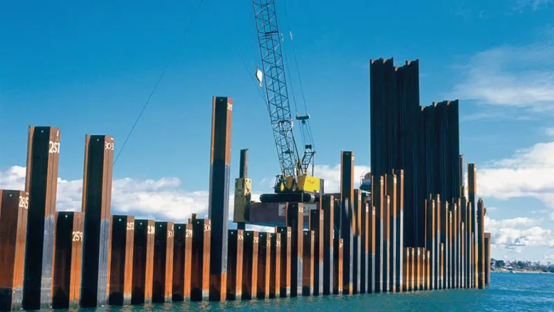
Above 12 m, pile length starts to control transport, handling and driving. Lengths over 15 m need a larger crane, a longer leader, and usually either a splice plan or a heavy-lift permit.
Handling, transport and splices
Length is the quiet cost driver. A 12 m pile fits a standard flat rack and a standard crawler crane. An 18 m pile needs breakbulk shipping, a 50 to 80 tonne crane and a road permit in most countries.
| Pile length | Transport | Handling | Note |
|---|---|---|---|
| up to 12 m | 40 ft flat rack or breakbulk | standard crawler | cheapest per tonne |
| 12 to 18 m | breakbulk or mafi | 50 to 80 t crane | check road permits early |
| 18 to 24 m | breakbulk only | 100 t and above | on-site splicing often cheaper |
| above 24 m | shipped in sections | twin crane | splice location is a design decision |
If you do splice, keep the joint away from the point of maximum moment and stagger the joints between neighbouring piles by at least a metre. A full penetration weld is normal for permanent work, and it needs a welder who has done it before. The lead time moves with the length as well: 12 m sections are usually in stock or rolled in two to three weeks, while 18 m sections often need a dedicated rolling slot. On a riverbank flood wall in Southeast Asia last year we shipped 12 m U-type piles for a 7 m retained height with one anchor, and the contractor spliced nothing. That was not luck. The height was known early, so the length was right from the first enquiry.
Tolerance compounds with height
One per cent out of vertical sounds harmless. At 3 m it is 30 mm. At 12 m it is 120 mm, and at that point the interlocks at the far end of the wall may not close at all.
The fix is procedural, not structural. Set a rigid guide frame, drive the first three piles and check them before the rest follow, and correct lean while the pile is still moving. Our note on vertical accuracy during driving covers the sequence. On tall walls I also recommend pre-boring the top few metres in dense gravel, because a pile that starts straight has a chance, and one that starts leaning does not.
What to put on the enquiry
Most of the rework I see comes from an enquiry that named a profile but not a height. Here is the list I send back.
| Field | Example | Why it matters |
|---|---|---|
| Clear retained height | 6.5 m | sets the moment and the section |
| Total pile length | 12.0 m | sets the mill cut and the freight |
| Required modulus | 2,400 cm³/m of wall | sets the profile family |
| Steel grade | S355GP | sets stress, weldability and price |
| Toe level | -6.0 m | sets length and driving resistance |
| Support type and level | one anchor at -1.0 m | sets the moment diagram |
| Corrosion allowance | 2 mm in the splash zone | sets thickness |
| Inspection | SGS, mill certificate, tensile test | sets the QA plan |
| Delivery split | 60 / 40 across two shipments | sets the shipping plan |
With those nine lines, I can quote a wall in a day and defend every number in it. Without them, I am guessing, and guessing on a 12 m pile is expensive for both of us.
My Take
Most enquiries I receive name a profile before they name a height, and that is backwards. The profile is an output. The height is the input, and it is the only input that changes everything downstream: the moment, the modulus, the embedment, the length, the crane and the freight.
When a contractor tells me he wants a Z-type 12 m pile, I ask two questions. What is the clear retained height, and what sits behind the wall? The answers usually change the order. Sometimes the 12 m becomes 9 m with an anchor, and the saving is bigger than any discount I could give on the steel. Sometimes a light U section that looked cheap per tonne fails the deflection check at 4.5 m, and the client is glad we found out before the piles were rolled.
My rule of thumb after fifteen years: choose the height, then let the height choose the section. If the section it chooses looks heavy, the answer is usually a change of support type, not a bigger pile.
Conclusion
Height sets the moment. The moment sets the section. The support type decides whether that section exists at all. Start with the clear retained height.