How Do Steel Sheet Pile Flange Width and Web Depth Affect Wall Performance?
Two dimensions hidden in the cross-section drawing decide whether your sheet pile wall stands straight or bulges. I have watched buyers pay dearly for ignoring them.
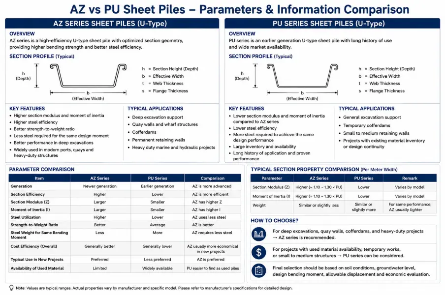
Flange width and web depth control how a steel sheet pile distributes bending stress. A deeper web raises moment of inertia and cuts deflection dramatically; a wider flange improves stability, interlock engagement, and handling strength. Together, these two dimensions define the stiffness you are actually buying.

When I walk customers from the Middle East, Australia, or West Africa through our factory in Liaocheng, the first thing I show them is not the rolling mill but a cross-section template. Most procurement disputes I have seen over “weak” walls trace back to one misunderstanding: the buyer compared sections by weight per meter or by thickness alone, while the real performance lives in the geometry between the flanges. Once you learn to read the flange width and web depth the way our engineers do, selecting a section becomes a ten-minute exercise instead of a gamble.
What Do Flange Width and Web Depth Actually Mean on a Steel Sheet Pile?
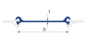
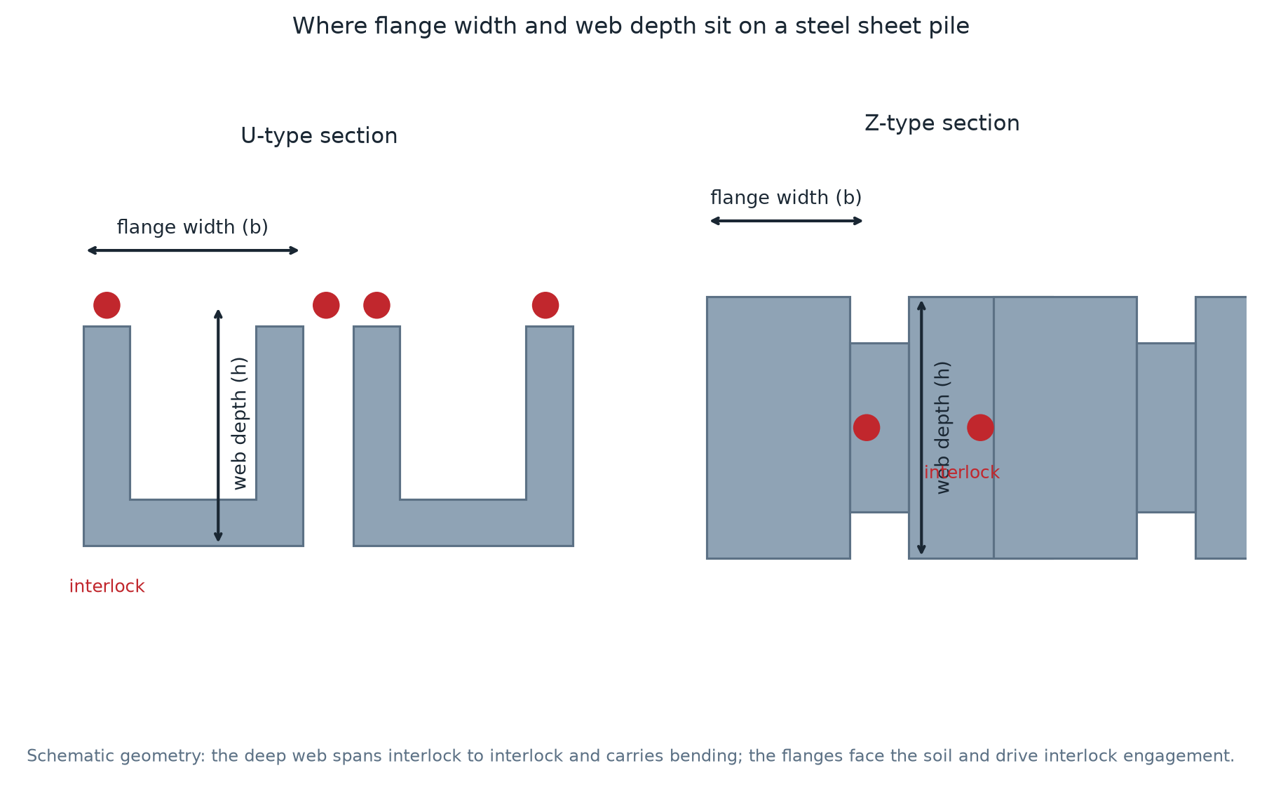
The flange is the outer plate face that presses directly against the retained soil, and the web is the deep plate connecting the two flanges across the wall’s bending axis. Flange width is measured across the pile’s exposed face, while web depth is the distance from interlock to interlock measured radially through the wall.
In plain terms: the web is the beam of your wall and the flange is its armor. A section with a deep web behaves like a deep girder and resists bending; the flange width decides how well the pile shares load with its neighbors through the interlocks and how safely crews can handle it on site.
The Geometry That Buyers Most Often Misread
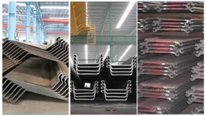
I receive RFQs every week that specify “600 mm wide sheet pile” without any mention of web depth, or a “depth of 400 mm” with no flange reference. Both readings are incomplete because the two dimensions work as a pair. In a Z-type section, the web depth largely sets the area moment of inertia of the wall, while the flange width sets how much of that stiffness survives the drive, when interlock rotation and pile lean try to steal it. In a U-type section, the effective stiffness also depends on whether the design assumes interlocks stay fixed or are allowed to slip, which is exactly the trap our previous article on steel sheet pile interlock types explains in detail.
The table below summarizes how our engineering team reads typical geometry ranges when a buyer sends us a spec sheet. Values are indicative ranges for common hot-rolled profiles rather than a catalog, because every mill’s series differs slightly.
| Geometry read | Typical hot-rolled range | What it signals to our engineers |
|---|---|---|
| Flange width | 500–750 mm | Wider flanges improve interlock engagement and wall flatness; easier alignment on long walls |
| Web depth | 200–500 mm | Deep webs raise moment of inertia sharply; the main lever on bending capacity |
| Web thickness | 6–16 mm | Often the first place mills save steel; check it against the yield strength assumptions in your grade |
| Flange-to-web ratio | Balanced profiles | Extreme ratios hint at either economy sections or heavy-duty marine sections |
When I audit a supplier quotation, I always rewrite the drawing callout as three numbers: flange width, web depth, and flange thickness. If any of the three is missing, the section cannot be evaluated, and I say so to the customer before they sign anything.
How Does Web Depth Drive Bending Stiffness and Moment Capacity?
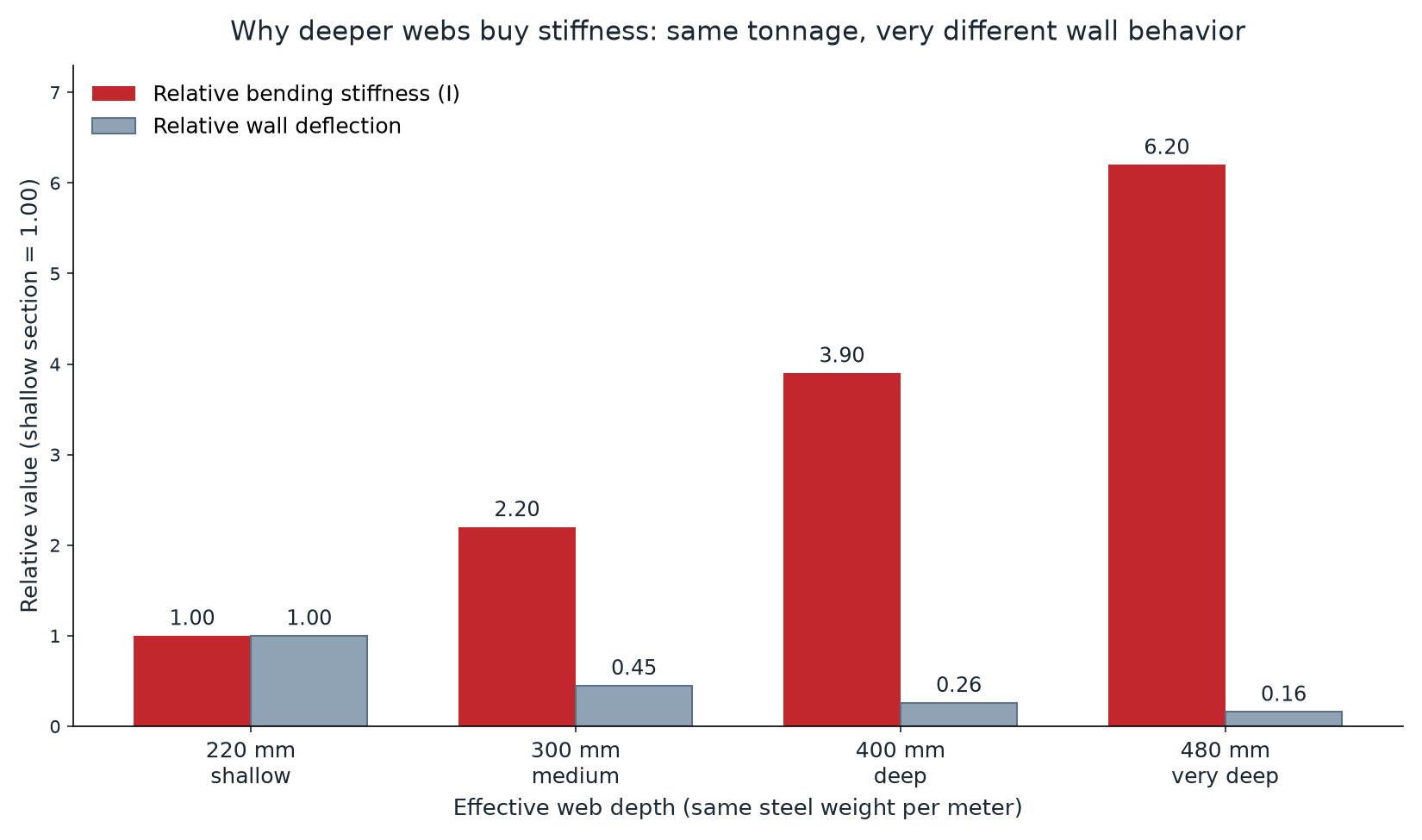
Web depth is the single most powerful geometric lever on wall performance, because stiffness grows roughly with the square of the distance between flanges, while material cost grows only linearly with steel area. That asymmetry is why deep sections feel almost unfairly efficient.
Doubling the effective web depth can roughly quadruple the bending stiffness of the same steel tonnage. For a cantilever wall, deflection falls in the same proportion, which is why I nearly always recommend trading shallow-but-thick sections for deeper profiles whenever the driving conditions allow.
Why a Deep Web Beats a Thick Web
The mathematics behind this is not exotic. The moment of inertia of a sheet pile section is dominated by the flange areas acting at a lever arm equal to roughly the web depth; move those flanges farther apart and the second moment grows with the square of that distance. The section modulus — the number every design engineer multiplies by allowable stress to get moment capacity — follows the same logic. I have quoted projects where switching from a 300 mm web to a 450 mm web of identical steel weight raised the design moment capacity by more than 70 percent, and the wall deflection prediction dropped by nearly half.
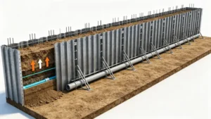
The practical consequence shows up in two ways. First, on tall walls — anything above six or seven meters of retained height — a deep web section often lets the client delete one row of anchors or walers, and anchor systems cost far more than the steel upgrade. Our guide on how wall height affects section selection walks through that trade with real numbers. Second, deep webs improve serviceability: for waterfront structures where crane rails sit directly on the capping beam, limiting deflection to a few tens of millimeters matters as much as ultimate strength.
| Web depth band | Relative bending stiffness (same weight) | Typical wall response I see on site |
|---|---|---|
| Shallow, 200–280 mm | 1.0 (baseline) | Noticeable deflection on walls above 5 m; usually needs anchoring early |
| Medium, 300–400 mm | 2–3.5 × baseline | The workhorse band for urban excavations and river walls |
| Deep, 420–500 mm | 4–7 × baseline | Tall quay walls and deep basements with minimal deflection |
One caution from experience: deep webs concentrate bending stress at the interlock line, so if the soil is boulder-rich, the flanges take the brunt of driving refusal. I pair deep sections with our soil-condition selection checklist before finalizing any recommendation.
Why Does Flange Width Matter for Wall Stability and Handling?
If the web is the muscle, the flange is the skeleton that keeps the wall square. Flange width governs how the wall resists torsional twist, how evenly it presents a bearing face to the soil, and how much contact area the interlocks have to share loads between adjacent piles.
Wider flanges give the wall lateral stability and give interlocks more metal-to-metal contact to transmit shear. Narrow-flange deep sections are wonderfully stiff in bending but need tighter alignment control; that trade-off decides what I recommend for long, straight walls.
The Stability Effects I Watch on Real Walls
The flange plays the same structural role it does on any plate girder — the flange of a beam is where bending stress concentrates, and on a sheet pile it is also the face the soil presses against. Three field behaviors tie directly to flange width. First, rotation: when a pile leans during driving, the interlock rotates, and a wider flange provides a longer contact band that resists that rotation and keeps the wall plumb. This is one reason straight-web sections, which have generous flat faces, dominate circular cell structures — our article on when engineers specify straight web sheet piles covers that special case. Second, flatness: a wall built from wide-flange sections presents a more even face to the soil, which reduces local stress concentrations where a crane rail or a fender panel mounts. Third, handling strength: flanges are what the lifting clamps and pile gates grip, and a robust flange tolerates repeated pitching without edge distortion.
| Flange width effect | Narrow flange (< 550 mm) | Wide flange (≥ 600 mm) |
|---|---|---|
| Interlock shear transfer | Adequate for standard walls | Better load sharing in long walls |
| Torsional stability | Needs tighter guide frames | Naturally plumb, fewer corrections |
| Handling and pitching | Lighter, faster cycles | More robust under repeated handling |
| Wall flatness | Small local variations | Even soil bearing face |
In my own quoting practice, I lean narrow-flange deep-web sections for braced excavations where a guide frame controls alignment anyway, and I lean wide-flange sections for riverside and marine walls installed from a barge, where every millimeter of natural stability saves correction time. That judgment has kept several of our Gulf-region clients from re-driving crooked walls.
How Do Flange and Web Geometry Influence Drivability?
A section that is perfect on paper can still fail in the ground if its geometry does not survive the hammer. Flange and web dimensions control how the pile transfers driving energy, how it reacts to obstructions, and how much the interlock suffers during penetration.
Thin webs at full depth drive faster but dent more easily against obstructions; stiff deep webs resist buckling but transmit less energy per blow. I match the geometry to the ground, not just to the structural calculation, and that habit has avoided most of the driving problems our clients report.
Reading the Ground Before Reading the Catalog
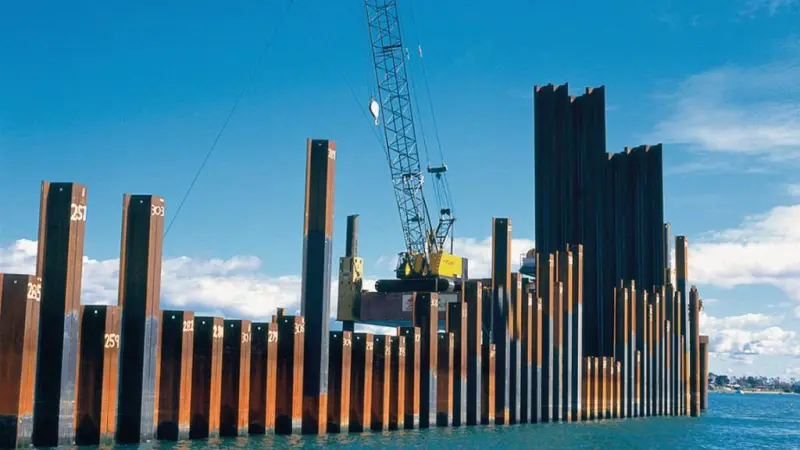
Drivability is a conversation between geometry and soil. In soft clays and loose sands, almost any hot-rolled section penetrates easily, so I optimize purely on structural stiffness and choose the deepest web the budget allows. In dense gravels or glacial tills, the picture flips: deep webs add flexural compliance that lets the toe wander, and the interlocks take repeated peening as the wall syncs through obstructions. There I often recommend a shorter, thicker-flange profile or a heavier hammer with lower blow counts, coordinated with the method comparison in our installation methods overview. The hammer itself matters as much as the section; using an underweight hammer on a stiff deep-web section spent one of our clients two extra mobilization days before we switched the rig.
Web thickness interacts with corrosion as well. Because sections lose thickness over their design life in aggressive ground or water, I check that the web retains enough thickness after the corrosion allowance — discussed in our corrosion protection guide — to carry the design bending moment at end of life. A section that passes the calculation at “as-new” thickness but fails at “corroded” thickness is not a bargain, whatever its price per ton.
| Ground condition | Geometry I steer clients toward | Reason from the site |
|---|---|---|
| Soft clay, loose sand | Deep web, standard flange | Drives easily; stiffness wins the day |
| Dense sand, gravel | Medium web, thicker flange | Resists toe wander and interlock peening |
| Boulder-rich till | Thicker flange, heavier section + rock duties | Survives obstruction strikes |
| Marine splash exposure | Deep web with corrosion allowance checked | End-of-life web must still carry moment |
Which Profile Should You Choose: Deep Web, Wide Flange, or Both?
By now the pattern should be clear: web depth buys bending performance, flange width buys stability and handling, and no single section maximizes both at minimum weight. The correct question is not “which profile is best” but “which imbalance does my wall tolerate best.”
I tell buyers to fix the wall height, soil profile, and corrosion environment first, then let the web depth fall out of the bending calculation and the flange width fall out of the installation method. A section chosen that way almost never needs a redesign mid-project.
A Selection Sequence That Survives Value Engineering
When a client asks me to review a specification, I follow the same sequence every time. Step one: confirm the retained height and water level, because they set the moment demand — the logic in our cantilever versus anchored wall comparison is the reference framework. Step two: read the soil report and set the drivability boundary. Step three: shortlist two or three sections whose web depths bracket the bending requirement, rather than one “hero” section. Remember that cold-formed sections present the same flange and web dimensions with tighter angular tolerances but thinner corners, so confirm which rolling route your spec implies before comparing offers. Step four: check each shortlisted section’s flange width against the installation method — barge work and long walls favor wider flanges. Step five: compare whole-life cost, not just tonnage, exactly as we do in our value engineering evaluation article.
| Project situation | Web depth bias | Flange width bias | Why this combination works |
|---|---|---|---|
| 8–12 m braced urban excavation | Deep | Moderate | Stiffness governs; guide frame controls alignment |
| Long river floodwall | Medium | Wide | Flatness and plumb matter over hundreds of meters |
| Marine quay with crane loads | Deep | Wide | Deflection limits and fender mounting both critical |
| Temporary cofferdam, reused piles | Medium | Robust flange | Survives multiple driving cycles |
Buyers who follow this sequence also communicate better with mills. When a request for quotation states flange width, web depth, and flange thickness explicitly, our mill can map it to a rolling series in hours, and the price you receive reflects a real section instead of a hopeful approximation. If you are preparing such an RFQ, our manufacturing process overview explains what the rolling mill can and cannot adjust for you.
My Take: Measure the Section, Not the Ton
After years of shipping steel sheet piles to contractors on four continents, my strongest conviction is that geometry literacy separates professional buyers from price-chasers. Tonnage tells you what you pay; flange width and web depth tell you what you get. I have seen identical tonnage budgets produce walls that differ by a factor of three in deflection, simply because one buyer read the cross-section and the other read the price list. When a client sends me a drawing with the three key dimensions called out, I know before any calculation that the project will run smoothly — and when those numbers are missing, I ask for them before I quote.
Conclusion
Read the web depth for stiffness, the flange width for stability, and match both to your soil and installation method. Geometry, not tonnage, is what your wall actually experiences.