You are on a construction site. The sheet piles are being driven, but how do you know the wall is straight, the interlocks are tight, and the piles have reached the correct depth? Quality control is not optional, it is essential.
Construction quality control1 for sheet pile installation2 includes pre-installation inspection of piles, monitoring verticality and alignment during driving, verifying interlock fit and water tightness, and documenting driving depth and resistance. QC ensures the wall meets design requirements and performs as intended for its design life.
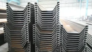
[^1] inspection during [sheet pile installation](https://www.steelpilinggroup.org/guidance/construction/pile-driving-installation-methods/)[^2]](https://placehold.co/600x400 "Sheet Pile Quality Control")](https://cnsteelplant.com/wp-content/uploads/2026/03/Article-application-2-2.webp)
I have supplied sheet piles for projects where QC made the difference between success and failure. A port project in the UAE required 100% interlock testing. A metro project in Singapore used real-time monitoring of verticality. Let me walk you through the key quality control1 steps for sheet pile installation2.
What pre-installation inspections1 are required for sheet pile quality control?
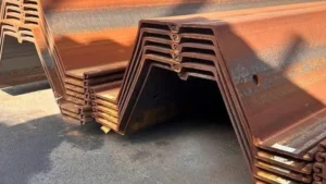
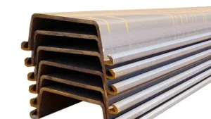
Pre-installation inspections verify that the sheet piles are in good condition before they go into the ground. This includes checking dimensions, straightness, interlocks, and coatings.
Pre-installation inspections include dimensional checks2 (width, height, thickness, length), straightness verification (bend and twist), interlock fit testing3 (ensure piles connect properly), coating inspection4 (thickness and adhesion for coated piles), and surface condition (no cracks, severe corrosion, or damage). Any damaged piles should be repaired or rejected before installation.
](https://cnsteelplant.com/wp-content/uploads/2026/03/Article-Application-Subway-1.webp)
Pre-Installation Inspection Checklist
Let me provide a comprehensive checklist for pre-installation inspection.
Dimensional Inspection
| Parameter | Tolerance | Inspection Method |
|---|---|---|
| Width | ±1% | Tape measure |
| Height | ±2% | Tape measure |
| Thickness | -0% / +10% | Caliper or micrometer |
| Length | +0 / +100 mm | Tape measure |
| Straightness (bend) | 1:500 | Straightedge or laser |
| Straightness (twist) | 1:500 | Straightedge or laser |
Interlock Inspection
- Interlock fit test: Connect sample piles to ensure proper engagement
- Interlock continuity: Check for obstructions or damage along the length
- Interlock lubricant: Apply if specified
Coating Inspection (for coated piles)
- Thickness: Measure with coating thickness gauge
- Adhesion: Cross-cut test or pull-off test
- Holidays (pinholes): Spark testing for FBE coatings
- Damage: Visual inspection for scratches or chips
Surface Condition Inspection
- Cracks: Visual inspection, dye penetrant for suspect areas
- Corrosion: Measure pitting depth, reject if excessive
- Weld splatter: Remove before driving
- Debris: Clean interlocks and surfaces
My Experience
For a port project, we rejected 3% of the sheet piles during pre-installation inspection due to interlock damage from shipping. The supplier replaced them, and the project stayed on schedule.
How to monitor verticality and alignment during sheet pile driving?
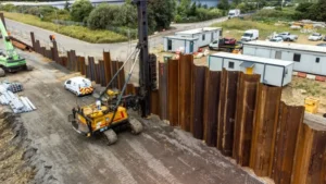
Monitoring verticality and alignment during driving ensures the wall is straight and plumb. Misaligned piles can cause interlock failure and water leakage.
Verticality1 is monitored using a digital level or inclinometer attached to the pile or the hammer. Alignment2 is monitored using guide frames and survey instruments. Typical tolerances are 1% of pile length for verticality (e.g., 50 mm over 5 m) and 50 mm over 10 m for alignment. Real-time monitoring allows immediate correction if piles start to tilt.
[^1] Monitoring")](https://cnsteelplant.com/wp-content/uploads/2026/03/Article-Application-River-Embankment-3.webp)
Verticality1 and Alignment2 Monitoring Methods
Let me explain the methods and tolerances for monitoring.
Verticality1 Monitoring Methods
| Method | Accuracy | Best For |
|---|---|---|
| Digital level3 on pile | ±0.1° | All piles |
| Inclinometer on hammer | ±0.05° | Deep piles, critical work |
| Laser plumb | ±0.05° | Long piles |
| Survey instrument (total station) | ±0.02° | Reference checks |
| Method | Accuracy | Best For |
|---|---|---|
| Guide frames | ±25 mm | Most projects |
| String line | ±50 mm | Short walls |
| Total station | ±10 mm | Critical alignment |
| GPS | ±50 mm | Long walls, remote sites |
Acceptance Tolerances
| Parameter | Tolerance | Example (10 m pile) |
|---|---|---|
| Verticality1 (plumbness) | 1% of length | 100 mm max |
| Alignment2 (wall straightness) | 50 mm over 10 m | 50 mm |
| Interlock gap | 5 mm max | N/A |
Corrective Actions for Misalignment4
| Problem | Cause | Corrective Action |
|---|---|---|
| Pile tilts forward | Soft soil, hard driving | Adjust hammer, use guide frame |
| Pile tilts sideways | Uneven soil, interlock friction | Adjust guide frame, pull and redrive |
| Wall drifts off line | Cumulative errors | Adjust guide frame, use pile gates |
| Interlock separation | Pile not plumb | Pull and redrive, use pile gate |
My Experience
For a metro project, we used a digital level on every pile. The operator checked verticality after each meter of driving. If the pile tilted more than 10 mm per meter, we stopped and adjusted before continuing.
What are the acceptance criteria for interlock fit1 and water tightness2?
Interlock fit and water tightness2 are critical for retaining walls and cofferdams. Acceptance criteria ensure the wall will hold water and resist soil pressure.
Acceptance criteria for interlock fit1 include full engagement of the interlock (no visible gap), ability to slide freely during driving, and interlock tension test3 results for cellular cofferdams. For water tightness2, acceptance criteria include visual inspection for gaps, water testing (filling the wall and measuring leakage), or dye testing for critical structures.
[^1] and [water tightness](https://counsilmanhunsaker.com/should-i-perform-a-water-tightness-test-on-my-pool-during-construction/)[^2] test on sheet pile wall](https://placehold.co/600x400 "Interlock Fit Test")](https://cnsteelplant.com/wp-content/uploads/2026/03/Article-Application-River-Embankment-5.webp)
Interlock and Water Tightness Acceptance Criteria
Let me provide specific acceptance criteria for interlock fit1 and water tightness2.
Interlock Fit Acceptance Criteria
| Check | Acceptance | Method |
|---|---|---|
| Interlock engagement | Full engagement, no gap | Visual inspection |
| Sliding resistance | Free movement during driving | Field observation |
| Interlock continuity | No obstructions along length | Mandrel test or visual |
| Interlock tension (cofferdams) | Minimum 200 kN/m | Laboratory test on samples |
Water Tightness Acceptance Criteria
| Application | Acceptance | Test Method |
|---|---|---|
| Cofferdam (temporary) | Leakage < 10 L/min per 100 m | Pump test |
| Quay wall (permanent) | No visible leakage | Visual inspection |
| Cut-off wall | Leakage < 1 L/min per 100 m | Dye test or flow meter |
| Flood wall | Watertight | Visual inspection |
When to Test
- Interlock fit: Test samples from each delivery lot
- Water tightness: Test after installation, before backfill
- Critical structures: Test after driving and after backfill
Common Interlock Problems
| Problem | Cause | Corrective Action |
|---|---|---|
| Interlock won't engage | Debris, damage | Clean or repair interlock |
| Interlock too tight | Misalignment, bent pile | Adjust alignment, pull and redrive |
| Interlock too loose | Worn interlock | Replace pile, add sealant |
| Gap in interlock | Poor driving | Inject sealant, weld repair |
My Experience
For a cofferdam project, we performed water tightness2 testing after installation. The leakage was 5 L/min per 100 m, which was within the 10 L/min specification. The client accepted the wall.
How to document and verify sheet pile driving depth and resistance?
Documenting driving depth and resistance provides a record that the piles were installed as designed and that the soil conditions match the geotechnical report.
Documentation includes recording the final depth1 of each pile, the driving resistance2 (blow count for impact hammers, or penetration rate for vibratory hammers), and any unusual driving conditions (obstructions, refusal). Verification includes comparing actual depths to design depths, checking that piles reached the required tip elevation, and identifying any piles that require re-driving or extension.
](https://cnsteelplant.com/wp-content/uploads/2026/03/Article-Application-City-4.webp)
Documentation and Verification Methods
Let me explain what to document and how to verify.
Information to Document for Each Pile
| Data | Method | Format |
|---|---|---|
| Pile identification number | Marking on pile | Alphanumeric |
| Start time | Clock | Time |
| End time | Clock | Time |
| Final depth | Depth marker on pile | Meters |
| Driving resistance | Blow count or penetration rate | Blows per 250 mm or seconds per m |
| Plumbness | Level reading | % or mm/m |
| Alignment | Survey reading | mm from line |
| Observations | Field notes | Text |
Driving Resistance Records
| Hammer Type | Record | Units |
|---|---|---|
| Impact hammer | Blow count | Blows per 250 mm |
| Vibratory hammer | Penetration rate | Seconds per meter |
| Press-in | Press-in force | kN |
Verification Checklist
- Final depth ≥ design depth
- Driving resistance within expected range
- No unexpected obstructions
- Pile plumbness within tolerance
- Alignment within tolerance
- Interlock engagement confirmed
Non-Conformance Actions
| Problem | Action |
|---|---|
| Pile does not reach depth | Splice extension, re-drive |
| Pile refuses before depth | Pre-drill, use larger hammer |
| Pile drives too easily | Check design, add friction piles |
| Pile out of tolerance | Pull and re-drive, adjust guide frame |
My Experience
For a port project, we maintained a driving log for every pile. The log showed that 98% of piles reached design depth within tolerance. The remaining 2% required re-driving or extension. The documentation was submitted to the engineer for final acceptance.
Conclusion
Quality control for sheet pile installation1 includes pre-installation inspection2, verticality and alignment monitoring, interlock fit verification, and depth documentation. Following these QC steps ensures the wall meets design requirements and performs as intended.
-
Understanding best practices can enhance your installation process and ensure structural integrity. ↩ ↩ ↩ ↩ ↩ ↩ ↩ ↩ ↩ ↩ ↩ ↩
-
Exploring this topic can help you implement effective inspection strategies to avoid costly mistakes. ↩ ↩ ↩ ↩ ↩ ↩ ↩ ↩ ↩ ↩ ↩ ↩ ↩ ↩
-
Learning about the interlock tension test can provide insights into maintaining the strength and durability of cofferdams. ↩ ↩ ↩
-
Learn about practical solutions to address misalignment issues, ensuring project success and safety. ↩ ↩