I have seen anchored sheet pile walls fail because the tie rods were not designed properly. It is a critical part of the system. Many people focus only on the sheet piles, but the tie rods are what hold the wall in place.
Designing a tie rod system involves calculating the anchor force from the earth pressures, selecting the correct rod diameter, and ensuring the connections and anchorage are strong enough. The rod must resist tension without yielding, and the anchor block must provide enough passive resistance.
You might think that picking a strong steel bar is enough. But the real challenge is in the details. The connections, the corrosion protection, and the anchor block location are all equally important. In this post, I will walk you through the entire process based on my experience and industry standards.
How to build a tie rod?
I often get questions about the practical side of tie rod installation. It is not just about the design on paper. It is about making it work in the field.
Building a tie rod starts with selecting the correct steel grade and diameter. Then, you fabricate the rod with threaded ends or clevises. On site, you connect the rod to the wale, route it back to the anchor block, and tension it to remove slack.
The Assembly Process
I have found that the assembly of tie rods is a precise process. It requires careful planning.
- Fabrication: The tie rods are usually made from round steel bars. The ends are often forged or threaded to allow for connections. In some cases, manufacturers use upset ends. This means they forge a larger diameter on the ends of the bar to create the threads. This is a great way to increase the strength at the critical connection points without making the whole rod thicker.
- Transportation and Handling: The rods are shipped to the site. They are often in long lengths. It is important to handle them with care to avoid bending.
- Site Preparation: The backfill behind the sheet pile wall is placed up to a level about 150mm below the final tie rod level. This provides a working platform.
- Supporting the Rods: The tie rods need to be supported at the correct level. If the rod sags, it can create unwanted bending stresses. I often recommend using sandbags or special supports placed every few meters. In some cases, we place the rods inside larger pipes. This is a good solution if the soil beneath the rod is expected to settle. The pipe gives the rod room to move freely.
- Connecting to the Wale: At the front wall, the tie rod is connected to the wale. The wale is a horizontal beam that spans across the sheet piles. It transfers the load from the wall to the tie rods. The connection is typically a clevis or a threaded nut.
- Connecting to the Anchor Block: At the other end, the rod is connected to the anchor block. This is often a concrete deadman or a sheet pile anchor wall. The connection needs to be robust and allow for slight movements.
Tensioning the System
After the rod is in place, you need to remove any slack. A loose tie rod will not work.
The simplest method is to use a turnbuckle or a nut at one end of the rod. You tighten it by hand to take out the slack. For larger diameter rods, you need a hydraulic cylinder. You apply a load of about 30 to 60 kN to pull the rod taut. Then you tighten the locknut to hold the tension. This ensures the rod is in pure tension when the earth pressure starts to push on the wall.
What are the methods of sheet piling installation?
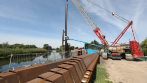
I have worked on many projects that used tie rods. The installation of the sheet piles themselves must be done right for the tie rods to work. There are a few key methods.
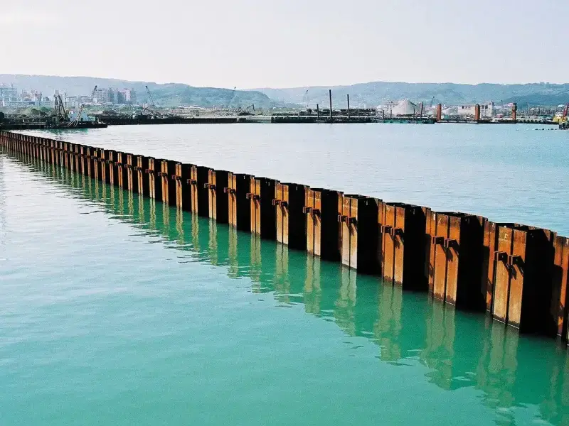
The main methods of sheet pile installation are impact driving, vibratory driving, pressing, and jetting. The choice depends on the soil conditions, the pile profile, and the proximity to existing structures.
Impact Driving
This is the oldest method. You use a heavy hammer to hit the top of the pile. The impact forces the pile into the ground. It is very effective in dense soils. However, it is very noisy. It also creates vibrations that can damage nearby buildings. I usually avoid this method in urban areas.
Vibratory Driving
This is my preferred method for many projects. You use a vibratory hammer that clamps onto the top of the pile. The hammer generates rapid vibrations. These vibrations reduce the friction between the pile and the soil. The weight of the pile and the hammer then drive it down. This method is fast and relatively quiet. It is ideal for loose to medium-dense sands.
Press-in Method
This is a quieter, vibration-free method. You use a large machine that pushes the piles into the ground using hydraulic jacks. It is a good option for projects close to sensitive structures. It works best in soft to medium soils. It can be slower than vibratory driving.
Jetting
In some cases, you can use water jets to help the pile penetrate the soil. High-pressure water is pumped down the sides of the pile. It loosens the soil and reduces friction. This method is usually combined with impact or vibratory driving.
What is the structure of a tie rod?
I see a tie rod as more than just a long steel bar. It is a system with several parts. Each part must be designed to handle the forces.
The structure of a tie rod system includes the tie rod itself, connections like clevises or turnbuckles, the wale at the sheet pile wall, and the anchor system at the back. It is a complete load path from the wall to the soil.
The Tie Rod
The main part is the steel bar. It is designed to carry the tension force. The bar must be made of high-strength steel. Common grades are S355, S460, and S500. The design must account for the rod’s net area, especially at the threaded sections, as this is the weakest point.
The Wale
The wale is a horizontal beam that runs along the sheet pile wall. It is usually made of two steel channels placed back-to-back. The tie rods pass between the channels. The wale collects the load from the sheet piles and transfers it to the tie rods. It is essentially a continuous beam that is supported by the tie rods.
The Connections
The connections are the most critical parts of the system. A failure at a connection is a failure of the whole system.
- Clevis and Pin: This is a common connection at the sheet pile wall. A clevis is a U-shaped fitting. A pin passes through the clevis and the tie rod eye. This allows for some rotation and prevents bending.
- Turnbuckle: This is used to adjust the length of the tie rod. It allows the contractor to tension the rod.
- Threaded Ends: Many tie rods have threads cut directly into the steel. The threads must be designed to be strong enough.
The Anchorage
The anchorage is the part that holds the tie rod in the ground. There are several types.
- Deadman Anchor: This is a concrete block that is buried in the ground. The tie rod connects to it. The resistance comes from the weight of the block and the passive pressure of the soil in front of it.
- Sheet Pile Anchor Wall: This is a short wall of sheet piles driven into the ground. The tie rod connects to this wall.
- Raking Piles: These are piles driven at an angle. The tie rod pulls on them. The resistance comes from the skin friction and end bearing of the piles.
What are two types of tie rods?
I often need to choose between different tie rod designs. The choice usually comes down to two main types: upset end rods and plain end rods.
The two primary types of tie rods are those with upset ends, where the rod is forged to increase the diameter at the threads, and those with plain ends, where the threads are cut directly into the rod of a constant diameter.
Upset End Tie Rods
This is the type I prefer for most marine or high-load projects. The ends of the rod are forged. This creates a larger diameter over the length that will be threaded. Because the threaded section is thicker, it is much stronger than a plain end. The tensile capacity of the threaded section often controls the design. By increasing the diameter at the threads, you can use a smaller, lighter rod for the main section. This saves on material costs. It also allows you to accommodate corrosion loss in critical areas without making the whole rod thicker.
Plain End Tie Rods
These are simpler and cheaper. The rod is a constant diameter. The threads are cut directly into the steel. The threaded section is the weakest point because it has a reduced cross-sectional area. Plain end rods are adequate for lighter loads or less aggressive environments. However, I have to be very careful with the design. The net area at the threads must be large enough to carry the full tension force.
| Feature | Upset End Rod | Plain End Rod |
|---|---|---|
| Manufacturing | Ends are forged to increase diameter. | Threads are cut directly into the rod. |
| Strength | Threads are stronger, capacity is higher. | Threads are weaker, capacity is limited. |
| Cost | More expensive to fabricate. | Less expensive. |
| Best Used For | High loads, marine environments, critical structures. | Light loads, less critical structures, temporary works. |
| Corrosion | Can accommodate corrosion with a larger diameter at the ends. | Corrosion reduces the section at the already weak threads. |
Conclusion
Designing a tie rod system is about understanding the forces, selecting the right materials, and ensuring proper installation. The rod, the wale, the connections, and the anchorage must all work together.