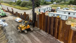
You are designing a deep excavation for a basement or a port wall. The excavation is 12 meters deep, and a cantilever wall would require embedment so deep it becomes impractical. You need anchors to hold the wall in place.
An anchored sheet pile wall1 uses tie rods or ground anchors2 to provide lateral support at one or more levels. The anchors reduce the required embedment depth, lower the bending moment in the piles, and allow much taller walls than cantilever designs. For depths over 6-8 meters, anchored walls are the standard solution.
[^1] diagram with tie rods and anchor piles](https://placehold.co/600x400 "Anchored Sheet Pile Wall Design")](https://cnsteelplant.com/wp-content/uploads/2026/03/Article-application-4-1.webp)
I have designed anchored sheet pile wall1s for port projects and deep excavations around the world. A port in the UAE used an anchored wall with two levels of tiebacks for 18 meters of water depth. A metro station in Southeast Asia used a single anchor system for a 12-meter excavation. Let me walk you through the design process for anchored sheet pile wall1s.
Sheet pile embedment depth1 rule of thumb
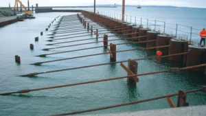
The rule of thumb for anchored sheet pile walls2 provides a quick starting point for estimating embedment depth1 before detailed analysis.
For anchored sheet pile walls2, the rule of thumb for embedment depth1 (D) is 0.5 to 0.8 times the exposed wall height (H). This is about half the embedment required for a cantilever wall of the same height. For soft clays, use the upper end of the range (0.7-0.8 H). For dense sands, use the lower end (0.5-0.6 H).
[^1] rule of thumb diagram](https://placehold.co/600x400 "Anchored Wall Embedment Rule")](https://cnsteelplant.com/wp-content/uploads/2026/03/Article-Application-City-5.webp)
Embedment Rules for Anchored Walls
Let me explain the factors that affect embedment depth1.
Base Rule
- D = 0.5 to 0.8 H
- H = exposed wall height (from top to dredge line)
Soil-Specific Rules
| Soil Type | D/H Range |
|---|---|
| Dense sand | 0.5 – 0.6 |
| Medium sand | 0.6 – 0.7 |
| Loose sand | 0.7 – 0.8 |
| Stiff clay | 0.6 – 0.7 |
| Soft clay | 0.7 – 0.8 |
Anchor Location Factor
- Anchor near top (2-3 m below top): D can be at lower end
- Anchor deeper (4-5 m below top): D may need to be increased
Water Table Factor
- Water table above dredge line: Add 10-20% to D
- Water table below dredge line: No adjustment
Example Calculation
Given:
- H = 12 m
- Soil = medium sand
- Water table at 3 m depth
Base D = 0.65 × 12 = 7.8 m
Water table factor: none (below dredge line)
Final D = 7.8 m
My Experience
For a port project with H = 18 m in dense sand, the rule gave D = 9 to 11 m. The detailed analysis gave D = 11 m, right in the middle of the range. The rule was a good starting point.
Sheet pile wall section
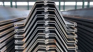
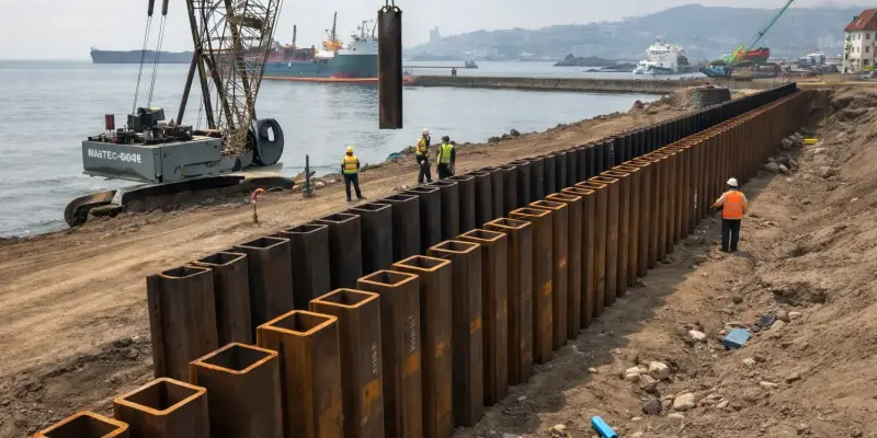
The sheet pile wall section is the steel profile that forms the wall. For anchored walls1, Z-type piles2 are commonly used because of their high structural efficiency.
Sheet pile wall sections for anchored walls1 are selected based on the required section modulus3 (S), which is determined by the maximum bending moment. Common sections for anchored walls1 include AZ 18 (S = 1,800 cm³/m) for moderate depths, AZ 26 (S = 2,600 cm³/m) for deeper walls, and AZ 34 or higher for very deep walls.
[^2]](https://placehold.co/600x400 "Sheet Pile Wall Section")](https://cnsteelplant.com/wp-content/uploads/2026/03/Article-Application-City-4.webp)
Section Selection for Anchored Walls
Let me provide guidance on selecting the right section for anchored walls1.
Common Z-Type Sections
| Section | Width (mm) | Height (mm) | Weight (kg/m) | S (cm³/m) | Max Wall Height |
|---|---|---|---|---|---|
| AZ 18 | 670 | 345 | 75.0 | 1,800 | 8-10 m |
| AZ 26 | 670 | 396 | 109.0 | 2,600 | 10-12 m |
| AZ 34 | 670 | 444 | 143.0 | 3,400 | 12-14 m |
| AZ 42 | 670 | 487 | 177.0 | 4,200 | 14-16 m |
| AZ 50 | 670 | 529 | 211.0 | 5,000 | 16-18 m |
Section Selection Guide
| Wall Height (H) | Required S (approx) | Recommended Section |
|---|---|---|
| 6 m | 1,000-1,500 | AZ 18 |
| 8 m | 1,500-2,000 | AZ 18 or AZ 26 |
| 10 m | 2,000-2,500 | AZ 26 |
| 12 m | 2,500-3,000 | AZ 26 or AZ 34 |
| 14 m | 3,000-3,500 | AZ 34 |
| 16 m | 3,500-4,000 | AZ 42 |
| 18 m | 4,000-4,500 | AZ 42 or AZ 50 |
U-Type for Anchored Walls
U-type piles4 can also be used for anchored walls1, but Z-type is more efficient.
| Section | Width (mm) | Weight (kg/m) | S (cm³/m) | Max Wall Height |
|---|---|---|---|---|
| U 400 x 170-15.5 | 400 | 76.1 | 2,470 | 8-10 m |
| U 600 x 180-13.4 | 600 | 81.6 | 3,820 | 10-12 m |
| U 600 x 210-18 | 600 | 106.2 | 5,730 | 12-14 m |
My Experience
For a 12 m anchored wall, we used AZ 26 sections. The section modulus3 of 2,600 cm³/m was more than adequate for the calculated moment of 2,100 cm³/m. The extra capacity provided a safety margin.
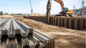
Steel sheet pile design example
A worked design example for an anchored sheet pile wall1 illustrates the complete design process using the free earth support method.
Consider an anchored sheet pile wall1 with 12 m exposed height, sand soil (φ = 35°, γ = 18 kN/m³), and a single anchor at 2 m below the top. The design determines the required embedment depth, anchor force, maximum bending moment2, and selects the pile section.
](https://cnsteelplant.com/wp-content/uploads/2026/03/Article-Application-City-2.webp)
Step-by-Step Design Example
Given Data
- Wall height (H): 12 m
- Anchor depth (a): 2 m below top
- Soil: Sand, γ = 18 kN/m³, γsub = 10 kN/m³, φ = 35°
- Water table: Below dredge line
- Steel: ASTM A572 Grade 503 (345 MPa yield)
- Factor of safety: 1.5 on passive resistance
Step 1: Earth Pressure Coefficients
Ka = tan²(45 – φ/2) = tan²(45 – 17.5) = tan²(27.5) = 0.27
Kp = 1/Ka = 3.70
Step 2: Active Pressure at Dredge Line
pa = Ka × γsub × H = 0.27 × 10 × 12 = 32.4 kPa
Step 3: Estimate Embedment Depth
Rule of thumb: D = 0.6 to 0.8 H = 7.2 to 9.6 m
Try D = 8.0 m
Step 4: Calculate Active Force
Active force above dredge line: F1 = 0.5 × pa × H = 0.5 × 32.4 × 12 = 194.4 kN/m
Location from dredge line: H/3 = 12/3 = 4.0 m
Step 5: Calculate Passive Force
Passive force below dredge line: Fp = 0.5 × Kp × γsub × D²
Fp = 0.5 × 3.70 × 10 × 8² = 0.5 × 3.70 × 10 × 64 = 1,184 kN/m
Location from dredge line: D/3 = 8/3 = 2.67 m
Step 6: Apply Factor of Safety
Reduced passive force = Fp / 1.5 = 1,184 / 1.5 = 789 kN/m
Step 7: Calculate Anchor Force
Sum moments about anchor (distance from top = a = 2 m):
Distance from anchor to dredge line = H – a = 12 – 2 = 10 m
Moment arm for active force = 4.0 + 10 = 14.0 m from anchor? Actually:
Take moments about anchor:
F1 × (H – a + H/3) = T × (H – a) + Fp_reduced × (D/3)
F1 × (12 – 2 + 4) = F1 × 14 = 194.4 × 14 = 2,722 kN-m/m
Fp_reduced × (D/3) = 789 × 2.67 = 2,107 kN-m/m
T × (H – a) = T × 10
2,722 = 10T + 2,107
10T = 615
T = 61.5 kN/m
Step 8: Check Horizontal Equilibrium
Active force = 194.4 kN/m
Passive + T = 789 + 61.5 = 850.5 kN/m > 194.4 OK
Step 9: Calculate Maximum Bending Moment
The maximum moment occurs where shear = 0. For this wall, Mmax = 320 kN-m/m
Step 10: Select Section
σallowable = 345 / 1.5 = 230 MPa = 230,000 kN/m²
S = 320,000 / 230,000 = 1,391 cm³/m
Select AZ 18 (S = 1,800 cm³/m) or AZ 26 for more capacity
Step 11: Total Length
Total = H + D = 12 + 8 = 20 m
Design Summary
- Section: AZ 18 (S = 1,800 cm³/m)
- Total length: 20 m
- Embedment: 8 m
- Anchor: Tie rods at 2 m depth, 61.5 kN/m → 184.5 kN at 3 m spacing
- Steel grade: ASTM A572 Grade 503
FHWA sheet Pile wall Design
The Federal Highway Administration (FHWA) provides comprehensive guidance for sheet pile wall design, including anchored walls, in their manuals and technical reports.
FHWA publications, including the "Steel Sheet Pile Design Manual1" and "Design and Construction of Mechanically Stabilized Earth Walls and Reinforced Soil Slopes," provide design methods, worked examples, and construction guidance for anchored sheet pile walls. These manuals are widely used for transportation and infrastructure projects.
](https://cnsteelplant.com/wp-content/uploads/2026/03/Article-application-4.webp)
Key FHWA Resources for Anchored Walls
Let me summarize the most important FHWA resources for sheet pile design.
FHWA Steel Sheet Pile Design Manual1
This manual covers:
- Earth pressure theory
- Cantilever and anchored wall design
- Seismic design
- Corrosion protection
- Installation methods
Key Design Methods in FHWA Manuals
- Free Earth Support Method2: For anchored walls with one anchor
- Fixed Earth Support Method: For anchored walls with fixed base
- Beam-on-Elastic-Foundation: For complex soil conditions
- Limit Equilibrium3: For overall stability
FHWA Design Steps for Anchored Walls
| Step | Description |
|---|---|
| 1 | Determine site conditions and soil parameters |
| 2 | Select anchor location and type |
| 3 | Calculate active and passive pressures |
| 4 | Determine embedment depth (free earth support method) |
| 5 | Calculate anchor force |
| 6 | Determine maximum bending moment |
| 7 | Select sheet pile section |
| 8 | Design anchor system (tie rods, anchor piles) |
| 9 | Check overall stability |
| 10 | Specify corrosion protection4 |
FHWA Recommended Factors of Safety
| Component | Factor of Safety |
|---|---|
| Passive resistance | 1.5 – 2.0 |
| Anchor capacity | 1.5 – 2.0 |
| Tie rod capacity | 1.5 – 2.0 |
| Overall stability | 1.3 – 1.5 |
My Experience
For a highway project with anchored sheet pile walls, we used the FHWA manual as our primary reference. The worked examples were clear, and the factor of safety recommendations matched the project requirements.
Conclusion
Anchored sheet pile walls1 are used for depths over 6-8 meters. Embedment depth is typically 0.5 to 0.8 times the exposed height. Z-type sections (AZ series) offer the best structural efficiency. The FHWA manual2 provides comprehensive design guidance.
-
Explore this link to understand the advantages and applications of anchored sheet pile walls in various construction projects. ↩ ↩ ↩ ↩ ↩ ↩ ↩ ↩ ↩ ↩ ↩ ↩ ↩ ↩ ↩ ↩ ↩
-
This resource is essential for engineers seeking detailed design guidance and best practices for sheet pile walls. ↩ ↩ ↩ ↩ ↩ ↩ ↩
-
Discover how this method helps assess overall stability in complex soil conditions. ↩ ↩ ↩ ↩ ↩
-
Understanding corrosion protection is vital for the longevity and safety of your sheet pile structures. ↩ ↩