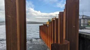
You are standing on a crowded city street. The buildings on both sides are old and sensitive. You need to dig a 10-meter deep hole for a new building foundation. The soil wants to collapse, and the buildings cannot move.
Steel sheet piles are the ideal solution for urban excavation1 projects. They provide a strong, interlocking wall that holds back soil and water while taking up minimal space. Sheet piles can be installed with low vibration and noise using press-in methods, making them suitable for sensitive urban sites. After the foundation is built, the piles can be extracted and reused.
[^2] being installed in tight urban site between buildings](https://placehold.co/600x400 "Urban Excavation Sheet Piles")](https://cnsteelplant.com/wp-content/uploads/2026/03/Article-Application-City-5.webp)
I have supplied sheet piles for urban excavation1s in dense cities across the Middle East and Southeast Asia. A metro project in Singapore used silent piling to install sheet piles next to historic buildings. A high-rise foundation in Dubai used braced sheet piles for a 15-meter basement. Let me walk you through the key considerations for using sheet piles in urban environments.
Steel sheet pile splice detail
Steel sheet pile splices are used when piles need to be longer than standard lengths. In urban excavations, splices are common because deep piles are needed but transport and handling limit individual pile lengths.
A steel sheet pile splice1 is a welded connection that joins two pile sections end to end. The splice must transfer the full bending moment and shear force from one section to the next. Common splice details include full penetration butt welds with backup bars, or splice plates welded to both sections. Splices should be staggered along the wall to avoid creating weak points at the same elevation.
[^1] detail diagram](https://placehold.co/600x400 "Steel Sheet Pile Splice Detail")](https://cnsteelplant.com/wp-content/uploads/2026/03/Article-Application-City-4.webp)
Splice Design and Installation
Let me explain the key aspects of sheet pile splices for urban projects.
Why Splices Are Needed
- Standard pile lengths: 12-18 m (shipping and handling limits)
- Deep urban excavations: Often require 20-30 m piles
- Solution: Splice two or more sections together
Splice Types
| Type | Description | Best For |
|---|---|---|
| Butt weld with backup bar | Full penetration weld, backup bar on inside | Permanent walls, high strength |
| Splice plate | Plates welded to both sections | Temporary walls, moderate loads |
| Interlock splice | Special interlock connection | Quick installation, temporary |
Splice Location Considerations
- Stagger splices along the wall (not all at same elevation)
- Avoid placing splices at points of high bending moment
- Locate splices at least 1 m away from brace points
- In urban sites, splices should be full strength for safety
Splice Installation Process
- Cut pile ends square and clean
- Align sections using guide frame
- Apply backup bar (for butt weld)
- Weld using qualified procedure
- Inspect weld (visual, UT for critical)
- Grind smooth for interlock clearance
My Experience
For a deep urban excavation in Dubai, we used full penetration butt welds with backup bars to splice 12 m piles into 24 m lengths. The splices were staggered by 2 m along the wall. All welds passed ultrasonic inspection.
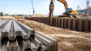
Sheet pile foundation detail
Sheet pile foundations in urban excavations require careful detailing to ensure the wall integrates properly with the permanent structure.
Sheet pile foundation details include the connection between the sheet pile wall and the building foundation, the embedment of piles below the excavation, and the interface with waterproofing systems1. In urban sites, the sheet piles often remain as permanent foundation elements or are extracted after the foundation is built.
[^2] detail diagram for urban excavation](https://placehold.co/600x400 "Sheet Pile Foundation Detail")](https://cnsteelplant.com/wp-content/uploads/2026/03/Article-Application-City-3.webp)
Foundation Interface Details
Let me explain the key details for sheet pile foundation2s in urban projects.
Temporary vs. Permanent
| Type | Description | Detail Considerations |
|---|---|---|
| Temporary | Piles extracted after foundation built | Allow extraction clearance, no waterproofing connection |
| Permanent | Piles left in place | Waterproofing connection, corrosion protection |
Foundation Connection Details
For Temporary Walls
- Piles driven to depth below excavation
- Foundation built inside the wall
- Gap between wall and foundation backfilled
- Piles extracted after foundation complete
For Permanent Walls
- Piles driven to design depth
- Concrete foundation cast against piles
- Waterproofing applied between pile and concrete
- Piles become part of permanent structure
Waterproofing Details
- Sheet piles are not waterproof on their own
- For basements, internal waterproofing is required
- Common methods: bentonite strips, external membranes, internal tanking
My Experience
For a high-rise basement in an urban site, we used temporary sheet piles that were extracted after the foundation was built. The detail included a 50 mm gap between the pile wall and the foundation, backfilled with lean concrete. The piles extracted easily after the backfill was removed.
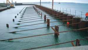
Metal shoring
Metal shoring is the use of steel beams, struts1, and sheet piles2 to support excavations in urban environments. It is the standard system for deep excavations in dense cities.
Metal shoring systems include sheet piles2 (the retaining wall), walers (horizontal beams), and struts1 or rakers (bracing). For deep urban excavations3, multiple levels of bracing are required. The system must be designed to resist soil and water pressures while minimizing space occupied inside the excavation.
[^4] system in urban excavation with [struts](https://www.soletanche-bachy.com/en/offer-portfolio/strut/)[^1] and walers](https://placehold.co/600x400 "Metal Shoring System")](https://cnsteelplant.com/wp-content/uploads/2026/03/Article-Application-City-2.webp)
Metal Shoring Components
Let me break down the components of a metal shoring4 system for urban excavations3.
Primary Components
| Component | Function | Typical Sections |
|---|---|---|
| Sheet piles | Retaining wall | U-type, Z-type |
| Walers | Distribute pressure to struts1 | W-beams, H-beams |
| Struts | Push against opposite walls | Pipe sections, H-beams |
| Rakers | Diagonal braces | H-beams |
| Tiebacks | Anchors behind wall | Grouted strands |
Shoring Types for Urban Sites
| Type | Description | Space Impact |
|---|---|---|
| Internal struts1 | Beams across excavation | Blocks access inside |
| Rakers | Diagonal from wall to foundation | Less obstruction |
| Tiebacks | Anchors behind wall | No internal obstruction |
Design Considerations for Urban Shoring
| Factor | Consideration |
|---|---|
| Adjacent buildings | Limit wall movement to 10-25 mm |
| Utilities | Avoid underground lines |
| Noise | Use vibratory or press-in methods |
| Vibration | Monitor adjacent structures |
| Access | Space for equipment and trucks |
Shoring Installation Sequence
- Drive sheet piles2
- Excavate to first brace level
- Install walers and struts1
- Excavate to next level
- Repeat until final depth
- Build permanent structure
- Remove bracing
- Extract sheet piles2
My Experience
For a metro station excavation in a dense urban area, we used a metal shoring4 system with four levels of internal struts1. The struts1 were designed with pre-load to minimize wall movement. The adjacent buildings experienced less than 15 mm settlement.
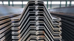
Steel seawall panels1 for sale
Steel seawall panels1 are not typically used for urban excavations. For urban excavation projects, sheet piles are the standard product, not seawall panels1.
For urban excavation projects, the products you need are steel sheet piles2 (U-type or Z-type), walers (H-beams or W-beams), and struts (pipe sections). Steel seawall panels1 are designed for coastal protection and have different interlocks than standard sheet piles. Always specify sheet piles for excavation support, not seawall panels1.
[^2] for excavation at storage yard](https://placehold.co/600x400 "Steel Sheet Piles for Excavation")](https://cnsteelplant.com/wp-content/uploads/2026/03/Article-Application-City-1.webp)
Products for Urban Excavation
Let me clarify the products you need for urban excavation projects.
Sheet Piles for Excavation
| Product | Type | Best For |
|---|---|---|
| U-type sheet piles | Symmetric, Larssen interlock | Moderate depths, curved alignments |
| Z-type sheet piles | Asymmetric, ball-and-socket | Deep excavations, straight walls |
| Cold-formed sheet piles | Lighter sections | Shallow excavations, temporary |
Steel for Bracing
| Product | Function |
|---|---|
| H-beams | Walers, rakers, struts |
| Pipe sections | Struts |
| W-beams | Walers |
Where to Buy
- Sheet pile manufacturers (ArcelorMittal, Nucor, Chinese mills)
- Steel service centers (cut to length)
- Used pile dealers (for temporary work)
What to Look For
- Mill certificates for new piles
- Interlock condition for used piles
- Straightness within tolerance
- Section modulus adequate for depth
My Experience
When contractors ask for "seawall panels1" for urban excavation, I explain that sheet piles are the correct product. Seawall panels have different interlocks and are not designed for the cyclic loading of excavation support.
Section modulus sheet pile
Section modulus is the most important structural property for sheet piles in urban excavations1. It determines how deep the excavation can be and how much bracing is needed.
Section modulus (S) is a measure of a pile’s bending strength. It is expressed in cm³ per meter of wall (cm³/m) or in³ per foot (in³/ft). For urban excavations1, the required section modulus2 is calculated from the maximum bending moment divided by the allowable stress. Higher section modulus2 means the wall can resist more bending force.
[^2] diagram for sheet pile](https://placehold.co/600x400 "Section Modulus Sheet Pile")](https://cnsteelplant.com/wp-content/uploads/2026/03/Article-Application-City-6.webp)
Section Modulus Guide for Urban Excavations
Let me provide a practical guide to section modulus2 for urban excavation projects.
Common Sections and Their Section Modulus
| Section | S (cm³/m) | Max Excavation Depth (Cantilever) | Max Excavation Depth (Braced) |
|---|---|---|---|
| U 400 x 100-10.5 | 1,080 | 3-4 m | 6-8 m |
| U 400 x 125-13 | 1,590 | 4-5 m | 8-10 m |
| U 400 x 170-15.5 | 2,470 | 5-6 m | 10-12 m |
| U 600 x 180-13.4 | 3,820 | 6-7 m | 12-15 m |
| AZ 18 | 1,800 | 4-5 m | 8-10 m |
| AZ 26 | 2,600 | 5-6 m | 10-12 m |
| AZ 34 | 3,400 | 6-7 m | 12-14 m |
| AZ 42 | 4,200 | 7-8 m | 14-16 m |
How to Use Section Modulus
- Calculate the maximum bending moment (Mmax) from geotechnical analysis
- Determine allowable stress (σallowable) for your steel grade
- Required S = Mmax / σallowable
- Select section with S ≥ required
Example for Urban Excavation
- Excavation depth: 10 m (braced)
- Soil: Sand, φ = 32°
- Mmax = 250 kN-m/m
- σallowable for A572 Gr50 = 345 / 1.5 = 230 MPa
- Required S = 250,000 / 230,000 = 1,087 cm³/m
- U 400 x 125-13 (S = 1,590) is adequate
My Experience
For a 12 m deep urban excavation, we calculated a required section modulus2 of 2,200 cm³/m. We selected AZ 26 with S = 2,600 cm³/m, providing a 15% safety margin. The wall performed perfectly.
Conclusion
Steel sheet piles1 are ideal for urban excavation projects. Use splices to achieve required pile lengths. Design foundation details for temporary or permanent walls. Use metal shoring with struts or tiebacks. Select sections based on required section modulus. For sensitive urban sites, use press-in methods2 to minimize noise and vibration.
-
Explore the advantages of Steel sheet piles for urban excavation, including efficiency and structural integrity. ↩ ↩ ↩ ↩ ↩ ↩ ↩ ↩ ↩ ↩ ↩ ↩ ↩ ↩ ↩ ↩ ↩ ↩ ↩ ↩
-
Learn how press-in methods can significantly reduce noise and vibration, making them ideal for sensitive urban environments. ↩ ↩ ↩ ↩ ↩ ↩ ↩ ↩ ↩ ↩ ↩
-
Find out about the unique challenges faced during urban excavations and how they are addressed. ↩ ↩
-
Explore this link to understand the fundamentals of metal shoring and its applications in urban construction. ↩ ↩