You are designing a new wharf or dock. Ships will berth alongside, cranes will operate on top, and the wall must hold back tons of soil and water for 50 years. Sheet piles are often the most economical choice.
Sheet pile design for wharf and dock walls requires consideration of water depth, soil conditions, berthing loads, crane loads, and corrosion protection. For depths up to 10 meters, cantilever walls may work. For deeper water, anchored walls1 with tie rods or ground anchors are used. Combination walls (H-piles with sheet piles) are used for the deepest applications.
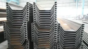
](https://cnsteelplant.com/wp-content/uploads/2026/03/Article-Application-River-Embankment-4.webp)
I have supplied sheet piles for wharves and docks across the Middle East, Southeast Asia, and Africa. A port project in the UAE used an anchored wall with AZ 26 piles for 18 meters water depth. A marina project in Southeast Asia used a cantilever wall with U-type piles for 6 meters water depth. Let me walk you through the design considerations for wharf and dock walls.
Sheet pile design calculation
Sheet pile design calculation for wharf walls follows limit equilibrium methods, with additional loads from berthing ships, crane operations, and wave action.
The design calculation involves determining active earth pressure from retained soil, water pressure from tides, surcharge loads from cranes and equipment, and berthing loads from ships. The required embedment depth is found by balancing moments, and the pile section is selected based on the maximum bending moment.
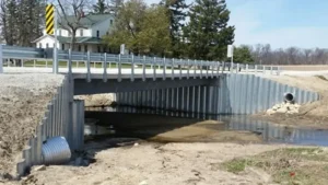
](https://cnsteelplant.com/wp-content/uploads/2026/03/Article-Application-River-Embankment-3.webp)
Step-by-Step Design Calculation
Let me walk through the calculation process for an anchored wharf wall.
Step 1: Determine Design Conditions
- Water depth at design high water: 12 m
- Freeboard (above water): 2 m
- Total wall height (H): 14 m
- Soil: Sand, γ = 18 kN/m³, γsub = 10 kN/m³, φ = 32°
- Surcharge: 20 kPa (container handling equipment)
- Berthing load: 50 kN/m distributed along the wall
- Anchor depth: 2 m below top
Step 2: Calculate Earth Pressure Coefficients
Ka = tan²(45 – φ/2) = tan²(29) = 0.307
Kp = 1/Ka = 3.255
Step 3: Calculate Active Pressure at Dredge Line
pa = Ka × γsub × H + γw × H + Ka × surcharge
pa = 0.307 × 10 × 12 + 10 × 12 + 0.307 × 20
pa = 36.8 + 120 + 6.1 = 162.9 kPa
Step 4: Include Berthing Load
Berthing loads are typically applied at the top of the wall as a line load.
Convert to equivalent pressure: pb = 50 kN/m / (effective height) ~ 5 kPa
Add to active pressure.
Step 5: Estimate Embedment Depth
Rule of thumb: D = 0.6 to 0.8 H = 8.4 to 11.2 m
Try D = 9.0 m
Step 6: Calculate Active Force
Active force above dredge line: F1 = 0.5 × 162.9 × 12 = 977 kN/m
Location from dredge line: 12/3 = 4.0 m
Step 7: Calculate Passive Force
Passive force below dredge line: Fp = 0.5 × Kp × γsub × D²
Fp = 0.5 × 3.255 × 10 × 9² = 1,319 kN/m
Step 8: Apply Factor of Safety
Reduced passive force = Fp / 1.5 = 879 kN/m
Step 9: Calculate Anchor Force
Sum moments about anchor:
T × (H – a) + Fp × (D/3) = F1 × (H – a + H/3)
Solve for T = 280 kN/m
Step 10: Calculate Maximum Bending Moment
Maximum moment occurs where shear = 0. For this wall, Mmax = 450 kN-m/m
Step 11: Select Pile Section
For ASTM A572 Grade 50 (345 MPa yield):
σallowable = 345 / 1.5 = 230 MPa = 230,000 kN/m²
S = 450,000 / 230,000 = 1,957 cm³/m
Select AZ 26 (S = 2,600 cm³/m) or AZ 18 (S = 1,800 cm³/m) is too low.
Step 12: Add Corrosion Allowance
Marine corrosion allowance: 2 mm over 50 years
Select AZ 26 with 13 mm thickness or AZ 26 with 15 mm for extra allowance.
Design Summary
- Section: AZ 26 (670 mm wide, 109 kg/m)
- Total length: 14 + 9 = 23 m
- Embedment: 9 m
- Anchor: Tie rods at 2 m depth, 3 m spacing, 840 kN each
- Steel grade: ASTM A690 (marine grade) recommended
Steel sheet pile design example
A worked design example from the US Army Corps of Engineers manual illustrates the complete design process for a wharf sheet pile wall.
Consider an anchored sheet pile wharf wall with 10 m water depth, sand soil (φ = 35°), and surcharge load from container cranes. The example walks through the free earth support method, determining embedment depth, anchor force, and required section modulus for a 50-year design life.
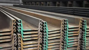
](https://cnsteelplant.com/wp-content/uploads/2026/03/Article-Application-River-Embankment-1.webp)
Detailed Design Example
Project Data
- Water depth: 10 m
- Freeboard: 2 m
- Total wall height (H): 12 m
- Anchor depth (a): 2 m below top
- Soil: Sand, γ = 18 kN/m³, γsub = 10 kN/m³, φ = 35°
- Surcharge: 25 kPa (crane loads)
- Steel: ASTM A690 (345 MPa yield, marine grade)1
- Factor of safety: 1.5 on passive resistance2
- Design life: 50 years
- Corrosion allowance: 2 mm3
Step 1: Earth Pressure Coefficients
Ka = tan²(45 – 35/2) = tan²(27.5) = 0.27
Kp = 1/Ka = 3.70
Step 2: Active Pressure at Dredge Line
pa = Ka × γsub × H + γw × H + Ka × surcharge
pa = 0.27 × 10 × 10 + 10 × 10 + 0.27 × 25
pa = 27 + 100 + 6.75 = 133.75 kPa
Step 3: Estimate Embedment Depth
Rule of thumb: D = 0.6 to 0.8 H = 7.2 to 9.6 m
Try D = 8.0 m
Step 4: Calculate Active Force
Active force above dredge line: F1 = 0.5 × 133.75 × 10 = 668.75 kN/m4
Location from dredge line: 10/3 = 3.33 m
Step 5: Calculate Passive Force
Passive force below dredge line: Fp = 0.5 × Kp × γsub × D²
Fp = 0.5 × 3.70 × 10 × 8² = 1,184 kN/m
Step 6: Apply Factor of Safety
Reduced passive force = Fp / 1.5 = 789 kN/m
Step 7: Calculate Anchor Force
Sum moments about anchor:
Anchor location from top: a = 2 m
Distance from anchor to dredge line: 10 m
Moment arm for active force: (H – a + H/3) = (12 – 2 + 3.33) = 13.33 m
Moment arm for passive force: D/3 = 8/3 = 2.67 m
T × (H – a) + Fp_reduced × 2.67 = F1 × 13.33
T × 10 + 789 × 2.67 = 668.75 × 13.33
10T + 2,107 = 8,915
10T = 6,808
T = 680.8 kN/m
Step 8: Check Horizontal Equilibrium
Active force = 668.75 kN/m
Passive force (reduced) + T = 789 + 680.8 = 1,469.8 kN/m > 668.75 OK
Step 9: Calculate Maximum Bending Moment
Maximum moment occurs where shear = 0. For this wall, Mmax = 420 kN-m/m
Step 10: Select Section
σallowable = 345 / 1.5 = 230 MPa = 230,000 kN/m²
S = 420,000 / 230,000 = 1,826 cm³/m
Select AZ 18 (S = 1,800 cm³/m) or AZ 26 (S = 2,600 cm³/m)
AZ 18 is close but slightly low. Choose AZ 26 for additional capacity.
Step 11: Add Corrosion Allowance
For 50-year life, add 2 mm to thickness.
AZ 26 standard: 13 mm thickness
Specify AZ 26 with 15 mm thickness for corrosion allowance.
Step 12: Total Length
Total = H + D = 12 + 8 = 20 m
Design Summary
- Section: AZ 26 with 15 mm thickness (ASTM A690)
- Total length: 20 m
- Embedment: 8 m
- Anchor: Tie rods at 2 m depth, 3 m spacing, 2,042 kN each
- Steel grade: ASTM A690 (marine grade)
Sheet pile walls
Sheet pile walls for wharves and docks come in three main types: cantilever walls, anchored walls, and combination walls. The choice depends on water depth and soil conditions.
Cantilever sheet pile walls1 rely on embedment for stability and are suitable for water depths up to 6-8 meters. Anchored sheet pile walls2 use tie rods or ground anchors to provide additional support, allowing water depths of 10-20 meters. Combination walls3 use H-piles with sheet piles between them and are used for water depths over 20 meters.
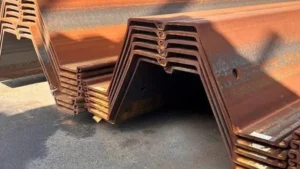
](https://cnsteelplant.com/wp-content/uploads/2026/03/Article-application-5.webp)
Comparison of Wall Types
Let me compare the three main wall types used in wharf construction.
Cantilever Walls
- How it works: Wall is embedded deep enough to resist rotation without anchors
- Water depth: Up to 6-8 m
- Advantages: Simpler construction, no anchors
- Disadvantages: Requires deep embedment, limited height
- Typical sections: U-type piles, lighter Z piles
- Cost: Lower for moderate depths
Anchored Walls
- How it works: Tie rods or ground anchors provide support at the top
- Water depth: 8-20 m
- Advantages: Taller walls, shallower embedment
- Disadvantages: Requires space for anchors, tie rod corrosion protection
- Typical sections: Z-type piles (AZ, PZC)
- Cost: Higher than cantilever, economical for deeper water
Combination Walls
- How it works: H-piles (king piles) with sheet piles between them
- Water depth: Over 20 m
- Advantages: Highest bending strength, can handle very deep water
- Disadvantages: Complex installation, higher cost
- Typical sections: HP 12 x 53 with sheet piles
- Cost: Highest
| Water Depth | Recommended Wall Type | Typical Section |
|---|---|---|
| 0-6 m | Cantilever | U 400 x 125 |
| 6-10 m | Anchored (single anchor) | AZ 18, PZC 18 |
| 10-15 m | Anchored (single or double) | AZ 26, PZC 26 |
| 15-20 m | Anchored (double anchor) | AZ 38, AZ 42 |
| 20-30 m | Combination | HP + sheet piles |
My Experience
For the port project in the UAE (18 m water depth), we used an anchored wall with two levels of anchors. The AZ 26 piles were driven to 27 m total length. For a marina project in Southeast Asia (6 m water depth), we used a cantilever wall with U 400 x 125 piles.
Cantilever sheet pile design example
Cantilever walls are the simplest type, suitable for moderate water depths where anchors are not needed or not feasible.
Consider a cantilever sheet pile wharf wall with 5 m water depth and 1 m freeboard (total H = 6 m). Soil is sand with φ = 32°, γ = 18 kN/m³. The design determines the required embedment depth and selects a U-type pile section1.
](https://cnsteelplant.com/wp-content/uploads/2026/03/Article-application-1.webp)
Detailed Cantilever Design Example
Project Data
- Water depth: 5 m
- Freeboard: 1 m
- Total wall height (H): 6 m
- Soil: Sand, γ = 18 kN/m³, γsub = 10 kN/m³, φ = 32°
- Water table: At mudline
- Steel: ASTM A328 (240 MPa yield)
Step 1: Earth Pressure Coefficients
Ka = tan²(45 – 32/2) = tan²(29) = 0.307
Kp = 1/Ka = 3.255
Step 2: Active Pressure2 at Dredge Line
pa = Ka × γsub × H + γw × H
pa = 0.307 × 10 × 5 + 10 × 5 = 15.35 + 50 = 65.35 kPa
Step 3: Estimate Embedment Depth
Rule of thumb: D = 1.0 to 1.5 H = 6 to 9 m
Try D = 7.0 m
Step 4: Calculate Net Pressure Diagram
Find depth z0 below dredge line where active pressure equals passive pressure:
Ka × γsub × (H + z0) + γw × (H + z0) = Kp × γsub × z0
0.307 × 10 × (5 + z0) + 10 × (5 + z0) = 3.255 × 10 × z0
(3.07 + 0.307z0) + (50 + 10z0) = 32.55z0
53.07 + 10.307z0 = 32.55z0
53.07 = 22.243z0
z0 = 2.39 m
Step 5: Calculate Forces
Active force above dredge line: F1 = 0.5 × 65.35 × 5 = 163.4 kN/m
Location from dredge line: 5/3 = 1.67 m
Active force from dredge line to z0: F2 = 0.5 × 65.35 × 2.39 = 78.1 kN/m
Location from dredge line: 2.39/3 = 0.80 m
Passive force below z0: F3 = 0.5 × (Kp × γsub × D) × D = 0.5 × 32.55 × 7 × 7 = 797.5 kN/m
Location from dredge line: D/3 = 2.33 m
Step 6: Check Moment Equilibrium
Take moments about dredge line:
F1 × 1.67 + F2 × 0.80 = F3 × 2.33
163.4 × 1.67 = 272.9
78.1 × 0.80 = 62.5
Total = 335.4
F3 × 2.33 = 797.5 × 2.33 = 1,858 (too high)
D is too large. Iterate to find D where moments balance.
After iteration: D = 7.2 m
Step 7: Calculate Maximum Bending Moment3
Maximum moment occurs where shear = 0. For this wall, Mmax = 210 kN-m/m
Step 8: Select Section
σallowable = 240 / 1.5 = 160 MPa = 160,000 kN/m²
S = 210,000 / 160,000 = 1,313 cm³/m
Select U 400 x 125-13 (S = 1,590 cm³/m)
Step 9: Total Length
Total = H + D = 6 + 7.2 = 13.2 m
Design Summary
- Section: U 400 x 125-13 (400 mm wide, 60 kg/m)
- Total length: 13.2 m
- Embedment: 7.2 m
- Steel grade: ASTM A328 (or ASTM A690 for marine)
My Experience
For a small wharf in Southeast Asia with 5 m water depth, we used a cantilever design with U 400 x 125 piles. The wall was in a sheltered harbor with minimal wave action. The piles drove easily and the wall has performed well for over a decade.
Conclusion
Sheet pile design1 for wharf and dock walls requires careful consideration of water depth, soil conditions, and operational loads. Cantilever walls2 work for moderate depths up to 6-8 m. Anchored walls are used for deeper water up to 20 m. Combination walls handle the deepest applications.
-
Understanding sheet pile design is crucial for effective wharf and dock construction, ensuring safety and durability. ↩ ↩ ↩ ↩ ↩
-
Exploring cantilever walls will provide insights into their benefits and suitability for various water depths in marine projects. ↩ ↩ ↩ ↩
-
Exploring bending moment factors can help you design safer and more efficient cantilever structures. ↩ ↩ ↩
-
Find out how to select the best wall type based on water depth and conditions. ↩ ↩