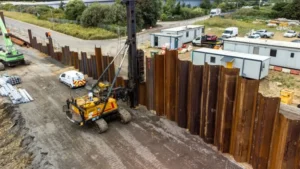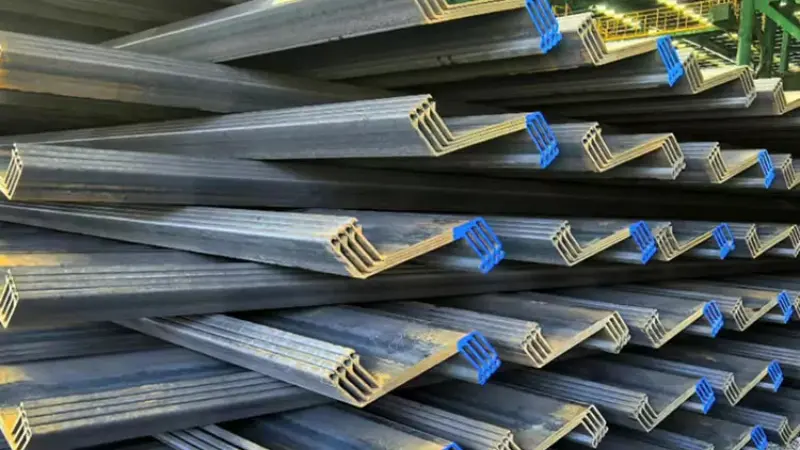
I have seen sheet pile walls lean dangerously after heavy rain. It is a scary sight. The wall looked fine during installation, but the soil behind it was pushing harder than expected. That experience taught me to never underestimate the forces at play.
Sheet pile wall stability is achieved by balancing the active earth pressure from the retained soil against the passive earth pressure that develops in front of the embedded portion of the wall. The calculation involves a rotational equilibrium analysis to find the required embedment depth, followed by structural checks for bending and deflection.
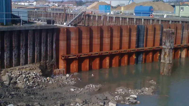
You might be tempted to just drive the piles deeper to be safe. I have done that myself on early projects. But that approach costs money and may not even solve the problem. The real issue is understanding how the soil and the wall interact. In the sections below, I will walk you through the key factors I consider when I calculate the stability of a sheet pile wall for my clients.
What is the allowable deflection for sheet pile wall?
Many contractors ask me about deflection limits. They want to know how much the wall can move without causing problems. The answer is not a single number. It depends on the project and what is next to the wall.
A common rule of thumb is to limit the maximum horizontal deflection to between 0.5% and 1% of the excavation depth. For example, a 5-meter-deep excavation would have an allowable deflection of 25 to 50 millimeters.
Factors That Control Deflection
The allowable deflection is not just a number I pull from a textbook. It is a project-specific value. I have to look at the surrounding structures and the serviceability requirements.
- Adjacent Structures: This is the biggest factor for me. If there is a building or a road right next to the excavation, the deflection must be very small. Even a few millimeters of movement can cause cracks in a building’s foundation. I often work with a geotechnical engineer to set a strict limit for these sensitive sites. A parametric investigation on deep excavation support systems found that to limit wall deflection to 0.5% of the excavation depth, it was necessary to use multiple levels of tieback anchors or struts.
- Wall Type and Support: The type of wall also makes a big difference. A cantilever wall will deflect more than an anchored wall. I have found that for cantilever walls, the deflection is often the controlling design factor, not the structural strength. Adding anchors or struts is the best way to reduce deflection.
- Soil Conditions: The soil stiffness is a key factor. A wall in stiff clay will deflect less than one in soft clay or loose sand. The passive pressure that develops in the soil depends on the soil’s stiffness. This is why I always insist on a good geotechnical report before I start any design.
How Deflection is Controlled
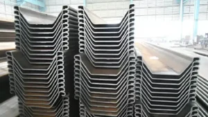
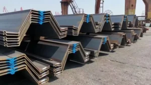
I use two main strategies to control deflection. The first is to increase the flexural stiffness of the wall. The deflection of a beam is inversely proportional to its flexural stiffness (EI), which is the product of the elastic modulus (E) and the moment of inertia (I). Choosing a thicker or deeper sheet pile profile increases the I value and reduces deflection. The second strategy is to add supports like anchors or struts. This changes the wall from a cantilever to a propped structure, which greatly reduces bending and deflection. I often recommend this for deeper excavations or when deflection limits are tight.
What is the formula for calculating a retaining wall?
There is no single formula for designing a retaining wall. It is a step-by-step process that involves several calculations. I use a method that looks at the forces on the wall and checks the structural capacity of the steel.
The design process starts with calculating the active and passive earth pressure coefficients, Ka and Kp. These are based on the soil’s friction angle, φ. The main goal is to find the embedment depth (D) that satisfies rotational equilibrium, meaning the driving moments from active pressure are balanced by the resisting moments from passive pressure.
The Step-by-Step Calculation
I follow a logical sequence when I design a retaining wall for a client. It ensures that I do not miss any critical steps.
- Define the Soil Parameters. The first step is to get the soil properties from a geotechnical investigation. I need the soil’s unit weight (γ), its angle of internal friction (φ), and the cohesion (c) if it is a clay soil. For design purposes, I often apply partial factors to these values to account for uncertainty.
- Calculate Earth Pressure Coefficients. I use Rankine’s theory for a simple calculation. The active coefficient is Ka = (1 – sin φ) / (1 + sin φ), and the passive coefficient is Kp = 1/Ka. For more accurate results, I sometimes use Coulomb’s theory, which accounts for wall friction.
- Determine the Embedment Depth. This is the most important step. I assume a depth for the pile below the excavation level. Then I calculate the horizontal active and passive stresses. I take moments about a point near the toe of the wall. I repeat this process, adjusting the depth until the sum of the moments is zero. This gives me the theoretical depth (d0). I then increase this depth by a factor of safety, often 20% to 40%, to get the final design depth.
- Check the Structural Capacity. Once I have the embedment depth, I analyze the wall as a beam. I find the maximum bending moment and shear force. Then I select a sheet pile profile that has a section modulus large enough to resist these forces without exceeding the steel’s yield strength.
Simplified Methods and Charts
In practice, the trial-and-error process can be time-consuming. I use simplified methods and charts to speed up the design. The simplified method for cantilever walls is based on a dimensionless analysis. The embedment depth depends on two things: the height of the wall (H) and the ratio of the passive and active earth pressures (Kp/Ka). This method is useful for quick estimates. For anchored walls, the analysis is more complex. The presence of the anchor introduces additional variables, such as the anchor location. The solution often requires solving a cubic equation, but charts are available to find the required depth and the anchor pull.
What do sheet pile walls depend for their support on?
The support for a sheet pile wall comes from the soil itself. The wall is not a rigid structure. It is a flexible member that relies on the surrounding ground to hold it in place.
Sheet pile walls depend on the passive earth resistance of the soil in front of the embedded portion of the wall. This passive resistance develops as the wall tries to move outward, and it counteracts the active pressure from the soil behind the wall.
The Mechanics of Support
I think of the support as a soil-structure interaction. The wall only works because the soil provides resistance. Without the soil’s passive pressure, the wall would simply tip over. The key factors that determine the support are the soil strength and the wall’s embedment depth. The passive pressure is directly related to the soil’s shear strength, which is represented by its friction angle (φ). A denser soil provides more support. A deeper embedment also provides more support because there is more soil to mobilize passive resistance.
Anchors and Struts as Additional Support
For deeper excavations or when the passive resistance alone is not enough, I add anchors or struts to provide extra support. These structures change how the wall is supported and greatly improve its stability. An anchored wall uses tie rods or ground anchors connected to a deadman or a rock bond zone. The anchor pulls the wall back, reducing the bending moment and the required embedment depth. A braced excavation uses internal struts and wales at multiple levels. This method is very effective for deep excavations in urban areas where deflection must be strictly controlled. I often recommend a support system based on the specific project requirements, such as the excavation depth and the proximity to adjacent structures.
The Role of Wall Flexibility and Soil Stiffness
A critical insight I have gained is that the support of a sheet pile wall is not a static phenomenon. The wall and the soil move together. The wall’s flexibility and the soil’s stiffness are both important. The amount the wall bends, or its deflection, is governed by its flexural stiffness (EI). A stiffer wall deflects less. The soil also acts as an elastic support. Rowe’s moment reduction method accounts for both sheet pile flexibility and soil stiffness. This method recognizes that a flexible wall will yield and allow the soil to redistribute its pressures. This can lead to a more economical design than a traditional rigid analysis.
Conclusion
Calculating sheet pile wall stability is about balancing forces and understanding the soil. The core support comes from the passive resistance of the soil, enhanced by anchors or struts where needed.