You are designing a sheet pile wall for a deep excavation. The soil report is complex, the water table is high, and the adjacent buildings are sensitive. You need reliable calculations to ensure the wall will not fail.
Sheet pile wall stability is calculated using limit equilibrium methods1 that balance active earth pressure from the retained side against passive resistance from the embedded side. For cantilever walls, the embedment depth must be sufficient to prevent rotation. For anchored walls, the anchor forces are calculated along with the required embedment.
[^2] calculations](https://placehold.co/600x400 "Sheet Pile Wall Stability Calculations")](https://cnsteelplant.com/wp-content/uploads/2026/03/Article-application-3-1.webp)
I have seen walls succeed and fail based on the quality of these calculations. The riverbank project in Southeast Asia used simple cantilever methods and worked perfectly. A port project in the Middle East required complex anchored wall analysis with multiple soil layers. Let me walk you through the calculation methods I have learned.
How to calculate steel in a retaining wall?
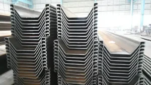
When engineers ask about "steel in a retaining wall," they usually mean the required section modulus1 and the weight of steel needed.
The steel in a sheet pile wall is calculated by determining the required section modulus1 from the bending moment2 and then selecting a pile section that meets or exceeds that requirement. The total steel tonnage is the weight per meter multiplied by the total length of the wall.
](https://cnsteelplant.com/wp-content/uploads/2026/03/Article-Application-River-Embankment-3.webp)
Step-by-Step Steel Calculation
Let me break this down into a process you can follow.
Step 1: Determine the Bending Moment
The first step is to calculate the maximum bending moment2 (Mmax) in the wall. This comes from the earth pressure analysis:
- For cantilever walls, Mmax occurs where shear is zero
- For anchored walls, Mmax occurs between the anchor and the bottom
- For multi-anchor walls, Mmax occurs in one of the spans
Mmax is expressed in kN-m per meter of wall.
Step 2: Calculate Required Section Modulus
The required section modulus1 (S) is:
S = Mmax / σallowable
Where σallowable is the allowable stress in the steel. For ASTM A3283 (240 MPa yield), with a factor of safety of 1.5:
σallowable = 240 / 1.5 = 160 MPa = 160,000 kN/m²
For higher strength steel, use the appropriate yield strength.
Step 3: Select a Pile Section
Manufacturers provide section modulus1 values for each pile type. For example:
- U-type 400×125: S = 1,500 cm³/m
- Z-type AZ 13: S = 1,300 cm³/m
- Z-type AZ 18: S = 1,800 cm³/m
- Z-type AZ 26: S = 2,600 cm³/m
Choose a section with S ≥ Srequired.
Step 4: Calculate Total Steel Weight
Total steel weight = (weight per meter of selected pile) × (total wall length) × (number of piles per meter of wall)
Weight per meter is from manufacturer data. For U-type 400×125, weight = 60 kg/m.
Number of piles per meter = 1 / (pile width in meters). For 400 mm width, 1 / 0.4 = 2.5 piles per meter.
Example:
For a 100 m long wall requiring 400×125 U piles:
- Piles per meter: 2.5
- Total piles: 100 m × 2.5 = 250 piles
- Each pile length: 13 m (from design)
- Total length: 250 × 13 = 3,250 m
- Weight per meter: 60 kg/m
- Total weight: 3,250 × 60 = 195,000 kg = 195 metric tons
What is the sheet pile shoring1 method?
Sheet pile shoring is a construction method used to support excavation2s and prevent soil collapse. It is one of the most common shoring systems in urban construction.
The sheet pile shoring1 method involves driving interlocking steel sheet piles around the perimeter of an excavation2 before digging begins. The piles form a continuous wall that holds back the soil and water. As excavation2 proceeds, internal bracing3 or tiebacks are installed to support the wall.
[^1] system with [internal bracing](https://gme-shields.com/sheeting-bracing/)[^3]](https://placehold.co/600x400 "Sheet Pile Shoring Method")](https://cnsteelplant.com/wp-content/uploads/2026/03/Article-Application-City-6.webp)
How the Shoring Method Works
Let me explain the process step by step.
Phase 1: Installation
Sheet piles are driven to the required depth using vibratory or impact hammers. The piles interlock to form a continuous wall. This is typically done from ground level before any excavation2.
Phase 2: Excavation and Bracing
Excavation begins. As soil is removed, the wall starts to deflect. Before deflection becomes excessive, bracing is installed. Common bracing systems include:
- Internal struts: Steel beams that push against opposite walls
- Rakers: Diagonal braces that bear against a foundation or slab
- Tiebacks: Grouted anchors drilled into the soil behind the wall
- Waling beams: Horizontal beams that distribute loads to braces
Phase 3: Continue Excavation
The process repeats: excavate to the next brace level, install bracing, continue down. Each brace level is installed before the excavation2 reaches the next level.
Phase 4: Construction
Once the excavation2 reaches final depth, the permanent structure is built. For temporary shoring4, the braces are removed as the permanent structure provides support.
Phase 5: Extraction (for temporary walls)
If the sheet piles are temporary, they are extracted after the permanent structure is complete. The piles can be reused on another project.
Advantages of Sheet Pile Shoring
- Fast installation
- Reusable (for temporary work)
- Provides water cutoff
- Works in tight urban sites
- Minimal ground loss if installed properly
Disadvantages
- Noise and vibration during installation
- Requires space for bracing
- Limited height for cantilever walls
- May need special methods in hard soil
My Experience
For the riverbank project, we used sheet pile shoring1 for the excavation2 behind the wall. The wall was permanent, so the piles remained. For a metro project, we used temporary sheet pile shoring1 with internal bracing3, then extracted the piles after the station was built.
What is the deflection limit1 for a sheet pile?
Deflection is a critical design consideration, especially when adjacent buildings or utilities are present.
The deflection limit1 for a sheet pile wall depends on the project and the surrounding structures. Typical limits are H/300 to H/200 for the wall itself, where H is the wall height. For walls adjacent to sensitive buildings, limits may be as tight as 10 to 25 mm total movement.
](https://cnsteelplant.com/wp-content/uploads/2026/03/Article-application-7.webp)
Understanding Deflection Limits
Let me explain the factors that determine allowable deflection.
General Guidelines
Industry practice provides typical limits:
- H/300 to H/200: Acceptable for most projects
- 25 mm to 50 mm: Common absolute limits
- For sensitive structures2: 10 mm to 15 mm
- For utilities: Based on pipe material and joint type
For a 10 m wall, H/200 = 50 mm. H/300 = 33 mm.
Factors Affecting Allowable Deflection
The allowable deflection depends on:
- Adjacent buildings: Historic or fragile buildings require tighter limits
- Utilities: Gas lines, water mains, and sewers have specific movement tolerances
- Ground conditions: Soft soils produce more deflection
- Wall type: Stiffer walls (Z piles, combination walls) deflect less
- Bracing: More bracing levels reduce deflection
Calculating Deflection
Deflection is calculated using beam-on-elastic-foundation methods or finite element analysis. Simple methods include:
- For cantilever walls: δmax ≈ (Ka γ H⁴) / (8 E I) for a uniform pressure approximation
- For anchored walls: Deflection is smaller and depends on anchor stiffness
Where:
- E = steel modulus (200,000 MPa)
- I = moment of inertia of the wall per meter
Controlling Deflection
If calculated deflection exceeds limits, you can:
- Use stiffer piles (higher I)
- Add more bracing levels
- Install bracing earlier in the excavation sequence
- Use tiebacks instead of internal bracing
- Consider a different wall type (slurry wall, secant piles)
My Experience
For a project adjacent to a historic building in the Middle East, the deflection limit1 was 15 mm. We designed a combination wall with H-piles and sheet piles, added an extra level of bracing, and used a very stiff tieback system. The measured deflection was 12 mm—within the limit.
How to calculate lateral load capacity1 of piles?
For sheet piles, lateral load capacity1 is not about bearing capacity—it is about the wall’s ability to resist lateral earth pressure without failing.
The lateral load capacity1 of a sheet pile wall is determined by the embedment depth2 and the passive soil resistance3. The wall must be embedded sufficiently so that the passive pressure can resist the active pressure from the retained side.
](https://cnsteelplant.com/wp-content/uploads/2026/03/Article-images-2.webp)
Calculating Lateral Capacity
Let me explain the fundamental calculation.
The Concept
A sheet pile wall is a vertical beam embedded in soil. The retained soil pushes laterally (active pressure). The soil in front of the wall resists (passive pressure). The wall is stable when the resisting forces exceed the driving forces.
For Cantilever Walls
The lateral capacity is determined by the embedment depth2. The wall must be long enough that the passive resistance develops fully before the wall rotates.
The calculation involves solving for D such that:
ΣM = 0 (sum of moments about the bottom equals zero)
This gives the required embedment depth2. Once D is known, the maximum lateral load the wall can resist is determined by the soil properties and the wall geometry.
For Anchored Walls
The lateral capacity is shared between the anchor and the passive soil. The calculation involves:
- Determine the anchor force required for equilibrium
- Verify that the anchor has sufficient capacity
- Verify that the embedment is sufficient to resist bottom kick-out
Simplified Method for Preliminary Design
For uniform soil conditions, a simplified method can be used:
D = (Ka × H) / (Kp – Ka) for cantilever walls in sand (simplified)
This gives a rough estimate of required embedment.
Factors Affecting Lateral Capacity
- Soil strength: Higher friction angle increases passive resistance
- Water table: Water reduces effective stress and capacity
- Wall stiffness: Stiffer walls distribute loads better
- Installation method: Driven piles may have different properties than drilled
Example Calculation
For a 6 m wall in sand (φ = 32°, Ka = 0.307, Kp = 3.25):
D = (0.307 × 6) / (3.25 – 0.307) = 1.842 / 2.943 = 0.63 m?
This simplified result is too low—it does not account for the distribution of pressures. Actual required D is 6 to 9 m. This is why detailed methods are used.
Detailed Methods
The proper calculation uses either:
- Net pressure method: Computes the pressure diagram and solves for D
- Free earth support method: For anchored walls
- Fixed earth support method: For stiff walls with fixed base
- Software: DeepEX4, GeoStudio, or other specialized programs
My Experience
For the riverbank project, we used the net pressure method5 with a factor of safety of 1.5 on passive resistance. The calculated embedment was 7.2 m. The contractor drove to 8 m to provide a margin. The wall has performed perfectly.
Conclusion
Sheet pile wall stability1 calculations balance active and passive earth pressures. Deflection limits protect adjacent structures. Lateral capacity depends on embedment depth and soil strength. Always use site-specific soil parameters.
-
Understanding the factors affecting sheet pile wall stability is crucial for safe and effective construction practices. ↩ ↩ ↩ ↩ ↩ ↩ ↩ ↩ ↩ ↩ ↩ ↩ ↩ ↩ ↩ ↩
-
Explore how embedment depth influences the performance and safety of pile structures in various soil conditions. ↩ ↩ ↩ ↩ ↩ ↩ ↩ ↩ ↩ ↩ ↩ ↩ ↩
-
Learn about passive soil resistance to enhance your knowledge of soil mechanics and its impact on pile stability. ↩ ↩ ↩ ↩
-
Find out how DeepEX software can streamline your pile design process and improve accuracy in calculations. ↩ ↩
-
Gain insights into the net pressure method for accurate lateral load calculations, essential for engineering design. ↩