You are an engineer with a project that needs a retaining wall or excavation support. The soil report is on your desk, and you need to select and design sheet pile1s that are safe, economical, and constructible.
Steel sheet pile1 structural design involves determining earth pressures2, calculating required embedment depth, finding maximum bending moment, and selecting a pile section with adequate section modulus. The design must satisfy equilibrium, strength, and serviceability requirements. Safety factors of 1.5 to 2.0 are applied to passive resistance and anchor capacity.
[^1] structural design diagram for retaining wall](https://placehold.co/600x400 "Steel Sheet Pile Structural Design")](https://cnsteelplant.com/wp-content/uploads/2026/03/Article-application-1-1.webp)
I have designed sheet pile1 walls for projects around the world. The riverbank project in Southeast Asia used a cantilever wall. A port project in the Middle East used an anchored wall with tiebacks. Let me walk you through the complete structural design process for sheet pile1 walls.
Steel sheet pile design example
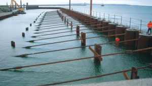
A worked design example is the best way to understand the sheet pile design process. Let me walk through a complete example for a cantilever wall.
Consider a cantilever sheet pile wall1 retaining 6 meters of soil. The soil is sand with unit weight 18 kN/m³ and friction angle 32 degrees. The water table is at 2 meters depth. The design determines the required embedment depth2, maximum bending moment3, and selects a U-type pile section.
](https://cnsteelplant.com/wp-content/uploads/2026/03/Article-images-2.webp)
Step-by-Step Design Example
Given Data
- Wall height (H): 6.0 m
- Soil: Sand, γ = 18 kN/m³ (above water), γsub = 10 kN/m³ (below water)
- Friction angle (φ): 32°
- Water table: 2.0 m below top
- Steel: ASTM A328 (240 MPa yield)
- Factor of safety: 1.5 on passive resistance
Step 1: Earth Pressure Coefficients
Ka = tan²(45 – φ/2) = tan²(45 – 16) = tan²(29) = 0.307
Kp = 1/Ka = 3.255
Step 2: Calculate Active Pressures
At z = 2 m (top of water table):
σv = γ × z = 18 × 2 = 36 kPa
pa = Ka × σv = 0.307 × 36 = 11.1 kPa
At z = 6 m (dredge line):
σv = (18 × 2) + (10 × 4) = 36 + 40 = 76 kPa
pa = Ka × σv + γw × 4 = 0.307 × 76 + 40 = 23.3 + 40 = 63.3 kPa
Step 3: Calculate Passive Pressures (below dredge line)
pp = Kp × γsub × z = 3.255 × 10 × z = 32.55z (kPa)
Step 4: Determine Embedment Depth (Iterative)
We need to find D such that the sum of moments about the bottom equals zero.
Try D = 7.0 m:
Calculate the net pressure diagram and moments.
The point of zero net pressure is found where pa = pp:
Ka × γsub × (H + z0) + γw × (H + z0) = Kp × γsub × z0
0.307 × 10 × (6 + z0) + 10 × (6 + z0) = 3.255 × 10 × z0
(18.42 + 3.07z0) + (60 + 10z0) = 32.55z0
78.42 + 13.07z0 = 32.55z0
78.42 = 19.48z0
z0 = 4.03 m
After full iteration, D = 7.2 m satisfies equilibrium.
Step 5: Calculate Maximum Bending Moment
The maximum moment occurs where shear = 0. For this wall, Mmax = 210 kN-m/m
Step 6: Select Pile Section
σallowable = 240 / 1.5 = 160 MPa = 160,000 kN/m²
S = Mmax / σallowable = 210,000 / 160,000 = 1,313 cm³/m
Select U 400 x 125-134 (S = 1,590 cm³/m)
Step 7: Total Pile Length
Total length = H + D = 6.0 + 7.2 = 13.2 m
Design Summary
- Section: U 400 x 125-134
- Steel grade: ASTM A328
- Total length: 13.2 m
- Embedment: 7.2 m
- Section modulus: 1,590 cm³/m (adequate)
USS Steel Sheet Piling Design Manual
The USS Steel Sheet Piling Design Manual is a classic reference that provides clear, practical guidance for sheet pile design. It remains valuable for engineers today.
The USS Steel Sheet Piling Design Manual was published by United States Steel in the 1960s. It covers earth pressure theory1, cantilever and anchored wall design2, cellular cofferdams3, and design charts4. The manual includes worked examples and design charts4 that are still relevant for preliminary design and checking calculations.
](https://cnsteelplant.com/wp-content/uploads/2026/03/Article-Application-River-Embankment-3.webp)
Key Sections of the USS Manual
Let me summarize the most useful sections of the USS manual.
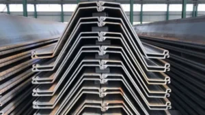
Chapter 1: Types and Properties
- U-type, Z-type, and straight web piles
- Section properties tables (weight, S, I)
- Steel grades and properties
Chapter 2: Earth Pressure
- Rankine and Coulomb theories
- Active and passive pressure coefficients
- Water pressure effects
- Surcharge loads
Chapter 3: Cantilever Walls
- Design methods
- Embedment determination
- Bending moment calculation
- Worked examples with design charts4
Chapter 4: Anchored Walls
- Free earth support method
- Fixed earth support method
- Anchor force calculation
- Worked examples with design charts4
Chapter 5: Cellular Cofferdams
- Design of circular and diaphragm cells
- Interlock stresses
- Filling materials
Chapter 6: Design Charts
- Quick reference for embedment depth
- Moment and anchor force charts
- Soil pressure diagrams
Why the USS Manual is Still Useful
| Feature | Benefit |
|---|---|
| Design charts | Quick preliminary design |
| Worked examples | Clear step-by-step guidance |
| Section properties | Complete tables for USS sections |
| Practical focus | Written for practicing engineers |
My Experience
I keep a PDF copy of the USS manual on my computer. The design charts4 for embedment depth are particularly useful for checking computer results. For a 6 m cantilever wall in sand, the chart gave D = 7.0 m, which matched our detailed analysis.
Sheet pile embedment depth1 rule of thumb
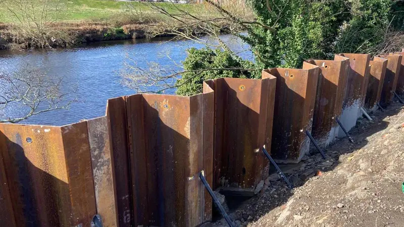
The rule of thumb for sheet pile embedment depth1 provides a quick starting point for design. It is useful for preliminary estimates and checking calculations.
For cantilever sheet pile walls2, the rule of thumb is embedment depth1 (D) = 1.0 to 1.5 times the exposed height (H). For anchored walls, D = 0.5 to 0.8 times H. Dense sands and stiff clays allow shallower embedment. Soft clays require deeper embedment. These rules are for preliminary design only; detailed analysis is required for final design.
[^1] rule of thumb diagram](https://placehold.co/600x400 "Sheet Pile Embedment Rule of Thumb")](https://cnsteelplant.com/wp-content/uploads/2026/03/Article-application-3-1.webp)
Embedment Rules by Wall Type and Soil
Let me provide detailed embedment rules for different conditions.
Cantilever Walls
| Soil Type | D/H Range |
|---|---|
| Dense sand | 1.0 – 1.2 |
| Medium sand | 1.1 – 1.3 |
| Loose sand | 1.2 – 1.5 |
| Stiff clay | 1.2 – 1.5 |
| Soft clay | 1.5 – 2.0 |
Anchored Walls
| Soil Type | D/H Range |
|---|---|
| Dense sand | 0.5 – 0.6 |
| Medium sand | 0.6 – 0.7 |
| Loose sand | 0.7 – 0.8 |
| Stiff clay | 0.6 – 0.7 |
| Soft clay | 0.7 – 0.9 |
Example Calculations
Cantilever wall, H = 6 m, medium sand:
D = 1.2 × 6 = 7.2 m
Total length = 6 + 7.2 = 13.2 m
Anchored wall, H = 12 m, medium sand:
D = 0.65 × 12 = 7.8 m
Total length = 12 + 7.8 = 19.8 m
My Experience
For the riverbank project (H = 6 m, medium sand), the rule gave D = 7.2 m. Our detailed analysis gave D = 7.2 m. The rule was accurate for these conditions.
Sheet pile design calculation
Sheet pile design calculation involves determining earth pressures, finding embedment depth1, calculating bending moment2, and selecting a section. The calculation can be done by hand, in Excel, or with specialized software.
The sheet pile design calculation uses limit equilibrium methods. For cantilever walls, the embedment depth1 is found by iterating until the sum of moments about the bottom equals zero. For anchored walls, the free earth support method3 provides a direct solution. The maximum bending moment2 is then used to select a pile section with adequate section modulus.
](https://cnsteelplant.com/wp-content/uploads/2026/03/Article-application-6.webp)
Design Calculation Steps
Let me outline the complete design calculation process.
Step 1: Calculate Earth Pressure Coefficients
Ka = tan²(45 – φ/2)
Kp = tan²(45 + φ/2)
Step 2: Calculate Active and Passive Pressures
pa = Ka × γ × z + γw × zw + Ka × q
pp = Kp × γ × z
Step 3: Determine Embedment Depth
For cantilever: Iterate D until ΣM = 0
For anchored: Use free earth support method3
Step 4: Calculate Anchor Force (for anchored walls)
T = (Active moment – Passive moment) / (H – a)
Step 5: Calculate Maximum Bending Moment
Find point where shear = 0
Integrate pressure diagram to that point
Step 6: Select Pile Section
Srequired = Mmax / σallowable
Select section with S ≥ Srequired
Step 7: Apply Safety Factors
Passive resistance: FS = 1.5 – 2.0
Anchor capacity: FS = 1.5 – 2.0
Steel strength: FS = 1.5
Key Formulas
| Parameter | Formula |
|---|---|
| Active pressure | pa = Ka × σv |
| Passive pressure | pp = Kp × σv |
| Section modulus | S = M / σallowable |
| Moment of inertia | I = S × (h/2) |
My Experience
I typically use Excel for sheet pile design calculations. The spreadsheet allows me to iterate on D quickly and try different soil layers. For complex projects, I verify with DeepEX or other software.
Conclusion
Steel sheet pile structural design involves earth pressure calculation1, embedment determination, and section selection. The USS Steel Sheet Piling Design Manual2 provides classic guidance. Use rules of thumb for preliminary design. Always perform detailed calculations for final design.
-
Understanding earth pressure calculations is crucial for ensuring the stability and safety of your structures. ↩ ↩ ↩ ↩ ↩ ↩ ↩ ↩ ↩ ↩ ↩ ↩
-
Exploring this manual will provide you with essential guidelines and best practices for effective steel sheet pile design. ↩ ↩ ↩ ↩ ↩ ↩ ↩
-
This method provides a direct solution for anchored walls, making it a key concept in effective sheet pile design. ↩ ↩ ↩ ↩
-
Design charts simplify complex calculations, making them invaluable for engineers in the field. ↩ ↩ ↩ ↩ ↩ ↩ ↩