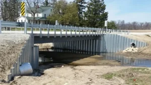
You are designing a new harbor or expanding an existing port. The water is deep, the ships are heavy, and the soil conditions are complex. You need to select the right sheet piles for the job.
The selection of steel sheet piles1 for harbor engineering depends on water depth, soil conditions, structural loads, and corrosion environment. U-type piles2 are suitable for moderate depths (up to 10 m) and curved alignments. Z-type piles are preferred for deeper water (10-20 m) and straight walls. Combination walls are used for the deepest applications (over 20 m).
](https://cnsteelplant.com/wp-content/uploads/2026/03/Article-Application-Port-4.webp)
I have supplied sheet piles for harbors across the Middle East, Southeast Asia, and Africa. A port project in the UAE used Z-type AZ 26 piles for an 18-meter quay wall. A marina project in Southeast Asia used U-type piles2 for curved berths. Let me walk you through how to select the right sheet piles for your harbor project.
Steel sheet pile design example
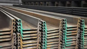
A design example helps illustrate the selection process. Let me walk through a typical harbor wall design.
Consider a harbor wall with 12 meters of water depth. The soil is sand with good properties. The wall will be anchored with tie rods. Required section modulus1 is calculated based on soil pressure, water pressure, and ship loads. For this example, the required section modulus1 is 2,600 cm³/m. The selected section is AZ 26, with weight 109 kg/m and width 670 mm.
](https://cnsteelplant.com/wp-content/uploads/2026/03/Article-Application-Port-3.webp)
Step-by-Step Design Example
Let me walk you through the design process for a harbor sheet pile wall.
Project Data
- Water depth: 12 m
- Dredge line: 12 m below mean sea level
- Soil: Dense sand, φ = 35°, γ = 18 kN/m³
- Surcharge: 20 kPa (container handling equipment)
- Wall type: Anchored sheet pile wall
- Anchor: Tie rods to anchor piles at 2 m below top
Step 1: Determine Earth Pressure Coefficients
Active pressure coefficient (Ka) = tan²(45 – φ/2) = tan²(45 – 17.5) = 0.27
Passive pressure coefficient (Kp) = 1/Ka = 3.70
Step 2: Calculate Active and Water Pressure
Active pressure at dredge line = Ka × γ × H = 0.27 × 18 × 12 = 58.3 kPa
Water pressure at dredge line = γw × H = 10 × 12 = 120 kPa
Total pressure at dredge line = 58.3 + 120 = 178.3 kPa
Step 3: Determine Required Embedment
For anchored walls, embedment depth is typically 0.5 to 0.8 times the exposed height.
Try D = 8 m (0.67 × H)
Passive resistance must exceed active pressure plus water pressure.
Step 4: Calculate Maximum Bending Moment
Using the free earth support method, the maximum moment occurs at approximately 0.4H below the anchor.
For this example, Mmax = 420 kN-m/m
Step 5: Calculate Required Section Modulus
For ASTM A572 Grade 502 steel (345 MPa yield), with safety factor 1.5:
σallowable = 345 / 1.5 = 230 MPa = 230,000 kN/m²
Srequired = Mmax / σallowable = 420,000 / 230,000 = 1,826 cm³/m
Step 6: Select Section
Selected section: AZ 26 (S = 2,600 cm³/m) or PZC 18 (S = 3,360 cm³/m)
Both provide adequate strength.
Step 7: Anchor Design
Anchor force = 280 kN per meter of wall
At 3 m spacing, each anchor = 840 kN
Anchor piles: Steel pipe piles, 20 m length, 500 mm diameter
Design Summary
- Sheet pile section: AZ 26 (670 mm wide, 109 kg/m)
- Total length: 20 m (12 m exposed + 8 m embedment)
- Anchor: Tie rods at 2 m below top, 3 m spacing
- Steel grade: ASTM A572 Grade 502 (marine grade A690 for corrosion)
Sheet pile installation methods
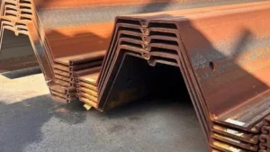
Sheet pile installation methods vary depending on site conditions, equipment availability, and project requirements.
The main sheet pile installation methods are vibratory driving1, impact driving2, press-in (silent piling)3, and jetting4. Vibratory hammers are the most common for sheet piles in harbor projects. Impact hammers are used for hard soils or obstructions. Press-in methods are used in sensitive urban areas where noise and vibration must be minimized.
](https://cnsteelplant.com/wp-content/uploads/2026/03/Article-Application-Port-2.webp)
Installation Method Comparison
Let me compare the different installation methods.
Vibratory Driving
- How it works: High-frequency vibrations reduce soil friction, allowing piles to sink under their own weight plus some downward force
- Best for: Sandy soils, granular materials, most harbor projects
- Advantages: Fast, relatively quiet, good for sheet piles
- Disadvantages: May not work in dense soils or with obstructions
- Equipment: Vibratory hammer mounted on crane or excavator
Impact Driving
- How it works: Heavy hammer strikes the pile top, driving it into the ground
- Best for: Dense soils, gravels, cobbles, hard driving conditions
- Advantages: Can penetrate hard soils, reliable
- Disadvantages: Loud, vibration can affect nearby structures
- Equipment: Diesel or hydraulic impact hammer
Press-In (Silent Piling)
- How it works: Hydraulic jacks press piles into the ground without impact or vibration
- Best for: Urban sites, sensitive structures, noise-restricted areas
- Advantages: Quiet, no vibration, precise alignment
- Disadvantages: Slower, higher cost, requires reaction force
- Equipment: Silent piler (press-in machine)
Jetting
- How it works: High-pressure water jets at the pile tip loosen soil, reducing resistance
- Best for: Loose sands, silts, where driving is difficult
- Advantages: Reduces driving resistance, can help penetrate loose soils
- Disadvantages: Creates slurry, not suitable for clays, can affect adjacent structures
Method Selection Guide
| Soil Condition | Recommended Method |
|---|---|
| Loose to medium sand | Vibratory |
| Dense sand | Vibratory or impact |
| Gravel, cobbles | Impact with pre-drilling |
| Soft clay | Vibratory or press-in |
| Stiff clay | Impact |
| Urban site, sensitive structures | Press-in |
My Experience
For the port project in the UAE, we used vibratory hammers for the sheet piles. The soil was dense sand, and the vibratory hammers worked well. For a section with cobbles, we switched to impact hammers and pre-drilled the holes.
Steel sheet pile installation1
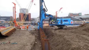
Steel sheet pile installation1 requires careful planning, proper equipment, and experienced crews to ensure a successful wall.
Steel sheet pile installation1 involves driving interlocking piles to the required depth using vibratory or impact hammers. Key steps include setting up guide frame2s, driving the first pile plumb, and maintaining alignment throughout the installation. For harbor projects, piles are often driven from barges or from land with extended leads.
](https://cnsteelplant.com/wp-content/uploads/2026/03/Article-Application-Port-1.webp)
Installation Steps
Let me walk you through the installation process.
Step 1: Site Preparation
- Clear the area of obstructions
- Establish alignment and elevation control
- Set up guide frame2s
Step 2: Guide Frame Setup
- Two parallel beams (wales) spaced slightly wider than pile width
- Provides alignment for the first piles
- Often mounted on the barge or on temporary piles
Step 3: Driving the First Pile
- First pile is critical—must be perfectly plumb
- Set in guide frame2, hang from crane
- Start driving with low energy, check plumbness frequently
- Drive to required depth or refusal
Step 4: Installing Subsequent Piles
- Hook next pile into the interlock of the previous pile
- Drive with the interlock facing the correct direction
- Maintain alignment with guide frame2
- Drive to the same elevation or penetration
Step 5: Interlock Checks
- Check interlocks periodically during driving
- Ensure they are fully engaged
- If a pile starts to tilt, adjust guide frame2 or use pile gates
Step 6: Finishing
- Cut piles to final elevation if needed
- Install capping beam or walers
- Install anchors or tiebacks
Common Installation Problems and Solutions
| Problem | Cause | Solution |
|---|---|---|
| Pile tilts | Soft soil, uneven driving | Use guide frame2, drive in stages |
| Interlock separation | Pile not plumb | Pull pile and re-drive, use pile gate |
| Hard driving | Obstruction, dense soil | Pre-drill, use impact hammer |
| Pile won’t reach depth | Underestimated penetration | Splice additional section, drive deeper |
My Experience
For the riverbank project, we used a vibratory hammer3 from a crane on land. The guide frame2 kept the piles aligned, and the installation went smoothly at 22 piles per day. The key was setting the first pile perfectly plumb.
Sheet pile guide frame
A sheet pile guide frame1 is essential for maintaining alignment and plumbness2 during installation, especially in marine environments.
A sheet pile guide frame1 consists of two parallel beams (wales) spaced slightly wider than the pile width. The frame is supported by temporary piles or mounted on the barge. It holds the piles in alignment while they are driven and prevents them from tilting or twisting.
[^1] at harbor construction site](https://placehold.co/600x400 "Sheet Pile Guide Frame")](https://cnsteelplant.com/wp-content/uploads/2026/03/Article-Application-Port-3-1.webp)
Guide Frame Design and Use
Let me explain how guide frames work and why they are critical.
Types of Guide Frames
| Type | Description | Best Use |
|---|---|---|
| Single stage | One set of wales at the top | Shallow walls, good alignment control |
| Double stage | Two sets of wales at different elevations | Deep walls, better alignment control |
| Full length | Template with multiple guide points | Precision work, critical walls |
| Barge-mounted | Frame attached to installation barge | Marine work, tide fluctuations |
Guide Frame Components
- Wales: Horizontal beams that guide the pile
- Spacers: Keep the wales at correct distance
- Supports: Hold the frame in position (temporary piles or barge structure)
- Pile gates: Mechanical devices that hold the pile in the interlock
Guide Frame Setup Steps
- Drive temporary support piles at the start of the wall
- Attach the wales to the support piles at the correct elevation
- Adjust spacing to match pile width
- Check alignment with survey instruments
- Begin driving piles, using the frame for alignment
Benefits of Using a Guide Frame
- Maintains wall alignment
- Prevents pile tilting
- Reduces risk of interlock separation
- Increases installation speed
- Improves final wall quality
My Experience
For the port project, we used a double-stage guide frame mounted on the barge. The lower frame was at the waterline, the upper frame at the deck level. This gave excellent control over plumbness even in tidal conditions.
Uncrimped sheet pile1
Uncrimped sheet pile1 refers to the condition of the pile interlock before installation. Understanding this helps ensure proper interlock engagement2.
Uncrimped sheet pile1 means the interlock has not been pre-crimped (compressed) to create friction. In most sheet pile installations, the interlocks are uncrimped, allowing the piles to slide freely during driving. For some applications, crimping is used to create friction that prevents the piles from sinking under their own weight in soft soils.
Crimping vs. Uncrimping
Let me explain the difference and when to use each.
Uncrimped Interlocks
- Description: Interlock is as-rolled, with normal clearance
- Behavior: Piles slide freely in the interlock
- Best for: Most applications, when piles need to be driven to depth
- Advantages: Easier driving, piles can be extracted
- Disadvantages: Piles may sink under their own weight in very soft soil
- Description: Interlock is compressed (crimped) to create friction
- Behavior: Piles have resistance to sliding
- Best for: Very soft soils where piles would sink under their own weight
- Advantages: Prevents uncontrolled sinking
- Disadvantages: Harder to drive, may damage interlocks
When to Use Uncrimped Piles
- Most harbor projects with competent soil
- When piles need to be driven to a specific penetration
- When piles will be extracted after use (temporary works)
- When using vibratory hammers4 (free movement helps vibration transfer)
When to Use Crimped Piles
- Very soft soils where piles sink under their own weight
- When piles must stay at a specific elevation before driving
- When using impact hammers (crimping helps maintain alignment)
My Experience
For the riverbank project, we used uncrimped piles. The soil was competent sand, and the piles drove well without sinking. For a project in soft clay, we specified crimped interlocks to prevent the piles from sinking too far before driving began.
Conclusion
Selecting sheet piles for harbor engineering requires careful consideration of water depth, soil conditions, and installation methods. U-type piles1 work for moderate depths, Z-type for deeper walls2. Use guide frames for alignment and choose uncrimped piles for most applications.
-
Explore this link to understand the specific applications and benefits of U-type piles in harbor engineering. ↩ ↩ ↩ ↩ ↩ ↩ ↩ ↩ ↩ ↩ ↩ ↩ ↩
-
This resource will provide insights into why Z-type piles are preferred for deeper applications in harbor construction. ↩ ↩ ↩ ↩ ↩ ↩ ↩ ↩ ↩ ↩ ↩ ↩ ↩ ↩ ↩
-
Learn about crimped interlocks and their specific applications in soft soil conditions for better project outcomes. ↩ ↩ ↩
-
Find out how vibratory hammers enhance the driving process of sheet piles, especially in uncrimped installations. ↩ ↩