You are designing a sheet pile wall. The soil on one side wants to push the wall over. The soil on the other side resists that push. Understanding how soil pressure works is the foundation of sheet pile design.
Soil pressure theory for sheet pile walls uses Rankine or Coulomb earth pressure equations1. Active pressure from the retained soil pushes the wall outward. Passive pressure from the soil in front of the wall resists movement. The wall must be embedded deep enough so passive pressure balances active pressure, with a factor of safety applied.
](https://cnsteelplant.com/wp-content/uploads/2026/03/Article-application-Cofferdam-Deep-Excavation-3.webp)
I have used soil pressure theory2 on every sheet pile project I have worked on. The riverbank project in Southeast Asia used Rankine theory for a cantilever wall. A port project in the Middle East used Coulomb theory for an anchored wall. Let me walk you through the fundamentals of soil pressure theory2 for sheet pile design.
Cantilever sheet pile wall Design Example
A cantilever sheet pile wall1 relies entirely on the soil below the excavation to hold it in place. It is used for moderate wall heights, typically up to 6 meters.
Consider a cantilever sheet pile wall1 retaining 5 meters of sand. Soil properties: γ = 18 kN/m³, φ = 35°, water table below the excavation. The design determines the required embedment depth2 and selects a pile section. The embedment is found by iterating until the active moment equals the passive moment about the bottom.
[^1] design example diagram](https://placehold.co/600x400 "Cantilever Sheet Pile Wall Design")](https://cnsteelplant.com/wp-content/uploads/2026/03/Article-application-4-1.webp)
Step-by-Step Cantilever Design Example
Given Data
- Wall height (H): 5.0 m
- Soil: Sand, γ = 18 kN/m³
- Friction angle (φ): 35°
- Water table: Below dredge line
- Steel: ASTM A328 (240 MPa yield)
Step 1: Earth Pressure Coefficients
Ka = tan²(45 – φ/2) = tan²(45 – 17.5) = tan²(27.5) = 0.27
Kp = 1/Ka = 3.70
Step 2: Active Pressure at Dredge Line
pa = Ka × γ × H = 0.27 × 18 × 5 = 24.3 kPa
Step 3: Estimate Embedment Depth
Rule of thumb: D = 1.0 to 1.5 H = 5.0 to 7.5 m
Try D = 5.5 m
Step 4: Find Depth of Zero Net Pressure
Find z0 below dredge line where active pressure equals passive pressure:
Ka × γ × (H + z0) = Kp × γ × z0
0.27 × (5 + z0) = 3.70 × z0
1.35 + 0.27z0 = 3.70z0
1.35 = 3.43z0
z0 = 0.39 m
Step 5: Calculate Forces
Active force above dredge line: F1 = 0.5 × pa × H = 0.5 × 24.3 × 5 = 60.8 kN/m
Location from dredge line: H/3 = 5/3 = 1.67 m
Active force from dredge line to z0: F2 = 0.5 × pa × z0 = 0.5 × 24.3 × 0.39 = 4.74 kN/m
Location from dredge line: z0/3 = 0.39/3 = 0.13 m
Passive force below z0: F3 = 0.5 × (Kp × γ × D) × D = 0.5 × 3.70 × 18 × 5.5 × 5.5 = 1,007 kN/m
Location from dredge line: D/3 = 5.5/3 = 1.83 m
Step 6: Check Moment Equilibrium
Take moments about dredge line:
F1 × 1.67 + F2 × 0.13 = F3 × 1.83
60.8 × 1.67 = 101.5
4.74 × 0.13 = 0.6
Total active moment = 102.1 kN-m/m
Passive moment = 1,007 × 1.83 = 1,843 kN-m/m (too high)
D is too large. Iterate to find D where moments balance.
After iteration: D = 5.0 m
Step 7: Calculate Maximum Bending Moment
Maximum moment occurs where shear = 0. For this wall, Mmax = 120 kN-m/m
Step 8: Select Section
σallowable = 240 / 1.5 = 160 MPa = 160,000 kN/m²
S = 120,000 / 160,000 = 750 cm³/m
Select U 400 x 100-10.5 (S = 1,080 cm³/m)
Step 9: Total Length
Total = H + D = 5 + 5 = 10 m
Design Summary
- Section: U 400 x 100-10.5
- Total length: 10 m
- Embedment: 5 m
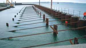
Anchored sheet pile wall design Example
An anchored sheet pile wall1 uses tie rods or ground anchors to provide support at the top. This reduces the required embedment depth2 and allows taller walls.
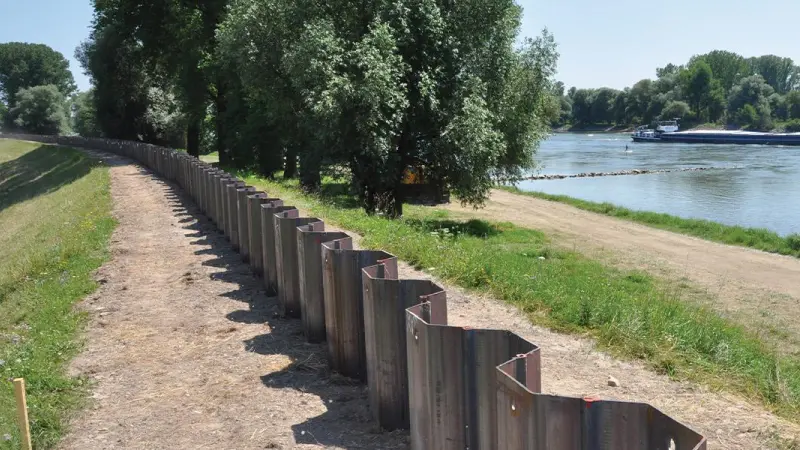
Consider an anchored sheet pile wall1 retaining 10 meters of sand. Soil properties: γ = 18 kN/m³, φ = 32°, water table below the excavation. The anchor is located 2 meters below the top. The design determines embedment depth2, anchor force, and selects a pile section.
[^1] design example diagram](https://placehold.co/600x400 "Anchored Sheet Pile Wall Design")](https://cnsteelplant.com/wp-content/uploads/2026/03/Article-Application-River-Embankment-1.webp)
Step-by-Step Anchored Design Example
Given Data
- Wall height (H): 10 m
- Anchor depth (a): 2 m below top
- Soil: Sand, γ = 18 kN/m³
- Friction angle (φ): 32°
- Water table: Below dredge line
- Steel: ASTM A572 Grade 50 (345 MPa yield)
Step 1: Earth Pressure Coefficients
Ka = tan²(45 – φ/2) = tan²(45 – 16) = tan²(29) = 0.307
Kp = 1/Ka = 3.255
Step 2: Active Pressure at Dredge Line
pa = Ka × γ × H = 0.307 × 18 × 10 = 55.3 kPa
Step 3: Estimate Embedment Depth
Rule of thumb: D = 0.5 to 0.8 H = 5 to 8 m
Try D = 6.0 m
Step 4: Calculate Active Force
Active force above dredge line: F1 = 0.5 × pa × H = 0.5 × 55.3 × 10 = 276.5 kN/m
Location from dredge line: H/3 = 10/3 = 3.33 m
Step 5: Calculate Passive Force
Passive force below dredge line: Fp = 0.5 × Kp × γ × D² = 0.5 × 3.255 × 18 × 6² = 1,055 kN/m
Location from dredge line: D/3 = 6/3 = 2.0 m
Step 6: Apply Factor of Safety
Reduced passive force = Fp / 1.5 = 1,055 / 1.5 = 703 kN/m
Step 7: Calculate Anchor Force
Sum moments about anchor (distance from top = a = 2 m):
Distance from anchor to dredge line = H – a = 10 – 2 = 8 m
Moment arm for active force3 = 3.33 + 8 = 11.33 m from anchor
F1 × 11.33 = T × 8 + Fp_reduced × 2.0
276.5 × 11.33 = 3,133
3,133 = 8T + 1,406
8T = 1,727
T = 216 kN/m
Step 8: Check Horizontal Equilibrium
Active force = 276.5 kN/m
Passive + T = 703 + 216 = 919 kN/m > 276.5 OK
Step 9: Calculate Maximum Bending Moment
The maximum moment occurs where shear = 0. For this wall, Mmax = 320 kN-m/m
Step 10: Select Section
σallowable = 345 / 1.5 = 230 MPa = 230,000 kN/m²
S = 320,000 / 230,000 = 1,391 cm³/m
Select AZ 18 (S = 1,800 cm³/m)
Step 11: Total Length
Total = H + D = 10 + 6 = 16 m
Design Summary
- Section: AZ 18 (S = 1,800 cm³/m)
- Total length: 16 m
- Embedment: 6 m
- Anchor: 216 kN/m → 648 kN at 3 m spacing
Sheet pile embedment depth1 rule of thumb
The rule of thumb for sheet pile embedment depth1 provides a quick starting point for design. It is based on soil type and wall type.
For cantilever walls2, embedment depth1 (D) is 1.0 to 1.5 times exposed height (H). For anchored walls, D is 0.5 to 0.8 times H. Dense sands require less embedment; soft clays require more. The rule is for preliminary design only. Final design requires detailed analysis.
[^1] rule of thumb table](https://placehold.co/600x400 "Sheet Pile Embedment Rule of Thumb")](https://cnsteelplant.com/wp-content/uploads/2026/03/Article-application-1.webp)
Embedment Rules by Soil and Wall Type
Cantilever Walls
| Soil Type | D/H Range | Example (H=5m) |
|---|---|---|
| Dense sand | 1.0 – 1.2 | 5.0 – 6.0 m |
| Medium sand | 1.1 – 1.3 | 5.5 – 6.5 m |
| Loose sand | 1.2 – 1.5 | 6.0 – 7.5 m |
| Stiff clay | 1.2 – 1.5 | 6.0 – 7.5 m |
| Soft clay | 1.5 – 2.0 | 7.5 – 10.0 m |
Anchored Walls
| Soil Type | D/H Range | Example (H=10m) |
|---|---|---|
| Dense sand | 0.5 – 0.6 | 5.0 – 6.0 m |
| Medium sand | 0.6 – 0.7 | 6.0 – 7.0 m |
| Loose sand | 0.7 – 0.8 | 7.0 – 8.0 m |
| Stiff clay | 0.6 – 0.7 | 6.0 – 7.0 m |
| Soft clay | 0.7 – 0.9 | 7.0 – 9.0 m |
My Experience
For the riverbank project (H = 6 m, medium sand), the rule gave D = 7.2 m. Our analysis gave D = 7.2 m. The rule was accurate for these conditions.
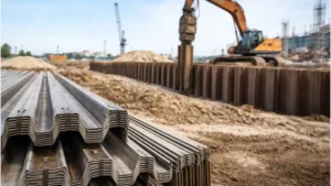
Sheet pile design example
A sheet pile design example brings together all the concepts: soil pressure, embedment depth1, bending moment2, and section selection.
Consider a sheet pile wall for a basement excavation. The wall height is 8 meters. The soil is sand with φ = 32° and γ = 18 kN/m³. The water table is at the excavation level. The wall is braced at one level. The design determines embedment depth1, brace force3, and selects a pile section.
](https://cnsteelplant.com/wp-content/uploads/2026/03/Article-application-3-1.webp)
Complete Design Example
Given Data
- Wall height (H): 8 m
- Brace depth: 2 m below top
- Soil: Sand, γ = 18 kN/m³, γsub = 10 kN/m³
- Friction angle (φ): 32°
- Water table: At dredge line
- Steel: ASTM A328 (240 MPa yield)
Step 1: Earth Pressure Coefficients
Ka = tan²(45 – 32/2) = tan²(29) = 0.307
Kp = 1/Ka = 3.255
Step 2: Active Pressure at Dredge Line
pa = Ka × γsub × H + γw × H = 0.307 × 10 × 8 + 10 × 8 = 24.6 + 80 = 104.6 kPa
Step 3: Estimate Embedment Depth
Rule of thumb for braced wall: D = 0.5 to 0.7 H = 4.0 to 5.6 m
Try D = 5.0 m
Step 4: Calculate Active Force
Active force above dredge line: F1 = 0.5 × pa × H = 0.5 × 104.6 × 8 = 418.4 kN/m
Location from dredge line: H/3 = 8/3 = 2.67 m
Step 5: Calculate Passive Force
Passive force below dredge line: Fp = 0.5 × Kp × γsub × D² = 0.5 × 3.255 × 10 × 25 = 407 kN/m
Location from dredge line: D/3 = 5/3 = 1.67 m
Step 6: Apply Factor of Safety
Reduced passive force = Fp / 1.5 = 407 / 1.5 = 271 kN/m
Step 7: Calculate Brace Force
Sum moments about brace (at 2 m depth):
Distance from brace to dredge line = 8 – 2 = 6 m
Moment arm for active force = 2.67 + 6 = 8.67 m
Moment arm for passive force = 1.67 m
F1 × 8.67 = T × 6 + Fp_reduced × 1.67
418.4 × 8.67 = 3,628
3,628 = 6T + 453
6T = 3,175
T = 529 kN/m
Step 8: Calculate Maximum Bending Moment
Mmax = 280 kN-m/m (from shear diagram)
Step 9: Select Section
σallowable = 240 / 1.5 = 160 MPa = 160,000 kN/m²
S = 280,000 / 160,000 = 1,750 cm³/m
Select U 400 x 170-13.5 (S = 2,120 cm³/m)
Step 10: Total Length
Total = H + D = 8 + 5 = 13 m
Design Summary
- Section: U 400 x 170-13.5
- Total length: 13 m
- Embedment: 5 m
- Brace force: 529 kN/m
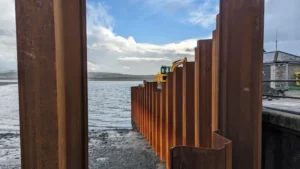
Sheet pile wall types
Sheet pile walls are classified by their support system: cantilever, anchored, or braced. The type determines the soil pressure distribution and design method.
Cantilever walls1 have no supports and rely on embedment for stability. Anchored walls2 use tie rods or ground anchors at one or more levels. Braced walls use internal struts or rakers. Cantilever walls1 are used for heights up to 6 m. Anchored and braced walls are used for taller excavations.
](https://cnsteelplant.com/wp-content/uploads/2026/03/Article-application-4.webp)
Comparison of Wall Types
Cantilever Walls
| Feature | Description |
|---|---|
| Support | None |
| Depth range | Up to 6 m |
| Soil pressure | Active on retained side, passive on embedded side |
| Design method | Net pressure method |
| Advantages | Simple, no bracing |
| Disadvantages | Limited height, deep embedment |
Anchored Walls
| Feature | Description |
|---|---|
| Support | Tie rods or ground anchors |
| Depth range | 6-20 m |
| Soil pressure | Active on retained side, anchor force at top |
| Design method | Free earth support or fixed earth support |
| Advantages | Taller walls, shallower embedment |
| Disadvantages | Requires space for anchors |
Braced Walls
| Feature | Description |
|---|---|
| Support | Internal struts or rakers |
| Depth range | Any depth |
| Soil pressure | Active on retained side, brace forces at each level |
| Design method | Beam-on-elastic-foundation or limit equilibrium |
| Advantages | No space required behind wall |
| Disadvantages | Obstructions inside excavation |
My Experience
For the riverbank project (H = 6 m), we used a cantilever wall. For a metro project (H = 15 m), we used an anchored wall with two levels of tiebacks. For a high-rise basement (H = 12 m) with no space behind the wall, we used a braced wall with internal struts.
Conclusion
Soil pressure theory1 is the foundation of sheet pile wall design2. Active pressure pushes the wall outward. Passive pressure resists movement. Cantilever walls work for heights up to 6 m. Anchored and braced walls are used for taller excavations. Always verify designs with detailed analysis.
-
Understanding soil pressure theory is crucial for effective sheet pile wall design and ensuring structural integrity. ↩ ↩ ↩ ↩ ↩ ↩ ↩ ↩ ↩ ↩ ↩ ↩ ↩
-
Exploring sheet pile wall design resources can enhance your knowledge and improve your engineering projects. ↩ ↩ ↩ ↩ ↩ ↩ ↩ ↩ ↩
-
Exploring brace force helps in understanding how to support sheet pile walls effectively during excavation and construction. ↩ ↩