You are designing a seawall, a revetment, or a coastal protection structure. The waves are constant, the tide fluctuates, and the soil is often soft. Getting the design parameters right is critical for the wall to survive storms and tides.
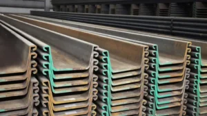
Sheet pile design for coastal engineering requires careful selection of soil parameters, water levels, wave loads, and corrosion allowances. Key parameters include soil friction angle, unit weight, water table, tidal range, and wave pressure. The design must consider both static conditions and extreme storm events.
](https://cnsteelplant.com/wp-content/uploads/2026/03/Article-Application-Port-3-1.webp)
I have worked on coastal projects from Southeast Asia to the Middle East. A seawall in Southeast Asia required careful consideration of tidal variations1. A port in the UAE needed wave load analysis for the design storm. Let me walk you through the key parameters and how to use them.
Sheet pile design Excel
Excel is a powerful tool for sheet pile design1, allowing engineers to perform iterative calculations quickly and check multiple scenarios.
Sheet pile design in Excel typically involves setting up active and passive pressure calculations2 for each soil layer, iterating to find the required embedment depth3, and calculating bending moments4 and anchor forces. Spreadsheets can handle variable soil layers, water levels, and surcharge loads, making them ideal for preliminary and final design.
[^1] excel spreadsheet example](https://placehold.co/600x400 "Sheet Pile Design Excel")](https://cnsteelplant.com/wp-content/uploads/2026/03/Article-Application-Port-4.webp)
Building a Sheet Pile Design Spreadsheet
Let me walk you through the key components of a sheet pile design1 spreadsheet.
| Input Parameters Section | Parameter | Value | Units |
|---|---|---|---|
| Wall height (H) | 6.0 | m | |
| Soil unit weight (γ) | 18.0 | kN/m³ | |
| Friction angle (φ) | 32 | degrees | |
| Cohesion (c) | 0 | kPa | |
| Water table depth | 2.0 | m | |
| Surcharge load | 10 | kPa |
Pressure Coefficients
For φ = 32°, Ka = 0.307, Kp = 3.255
| Active Pressure Calculation by Layer | Depth (m) | Soil Type | γ (kN/m³) | σ’v (kPa) | u (kPa) | σv (kPa) | pa (kPa) |
|---|---|---|---|---|---|---|---|
| 0-2 | Sand | 18 | 36 | 0 | 36 | 11.1 | |
| 2-6 | Sand (submerged) | 10 | 40 | 40 | 80 | 24.6 |
Embedment Iteration
The spreadsheet iterates on D until moment equilibrium is achieved.
| Output Section | Result | Value |
|---|---|---|
| Required embedment (D) | 7.2 m | |
| Total pile length | 13.2 m | |
| Maximum moment (Mmax) | 210 kN-m/m | |
| Required section modulus | 1,310 cm³/m |
Advanced Features
- Multiple soil layers
- Variable water levels (high tide, low tide, storm surge)
- Wave pressure calculations2
- Anchor force determination
- Factor of safety checks
- Graphical pressure diagrams
My Experience
I have used Excel for sheet pile design1 on many projects. For the riverbank project, we built a spreadsheet that handled the variable water levels from the tide. It allowed us to check both high tide and low tide conditions quickly.
Sheet pile Design Manual
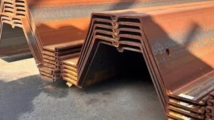
A sheet pile design manual is an essential reference for engineers, providing standardized methods, design examples, and guidance.
The most comprehensive sheet pile design manuals include the US Army Corps of Engineers Engineer Manual EM 1110-2-2504, the Pile Buck Steel Sheet Piling Design Manual1, and the ArcelorMittal Sheet Piling Handbook2. These manuals cover earth pressure theory3, design methods, installation, and corrosion protection.
](https://cnsteelplant.com/wp-content/uploads/2026/03/Article-Application-Port-2.webp)
Key Design Manuals and Their Content
Let me summarize the most important design manuals.
US Army Corps of Engineers EM 1110-2-25044
This is the gold standard for sheet pile design in the US and many other countries.
- Chapter 1: Introduction and design philosophy
- Chapter 2: Site characterization and soil parameters
- Chapter 3: Earth pressure theory
- Chapter 4: Cantilever wall design
- Chapter 5: Anchored wall design
- Chapter 6: Seismic design
- Chapter 7: Corrosion and durability
- Appendix: Worked examples
Pile Buck Steel Sheet Piling Design Manual1
This industry reference has been used for decades.
- Section properties for all common piles
- Earth pressure calculations
- Design examples for cantilever and anchored walls
- Installation guidance
- Cost estimating
ArcelorMittal Sheet Piling Handbook2
The European standard reference.
- Product range and properties
- Design methods (limit state and working stress)
- Worked examples
- Installation and handling
- Corrosion protection
How to Use a Design Manual
- Start with the design philosophy section to understand the approach
- Determine your site conditions and soil parameters
- Select the appropriate design method (cantilever, anchored)
- Follow the step-by-step calculations
- Use the worked examples to check your work
- Apply the recommended factors of safety
My Experience
For the port project, we used the USACE manual as our primary reference. The worked examples for anchored walls in sand matched our conditions closely. The manual provided clear guidance on selecting factors of safety and checking for seismic conditions.
Steel sheet pile design example
A worked design example helps illustrate the entire design process, from soil parameters to section selection.
Consider a cantilever sheet pile wall retaining 6 meters of sand. Soil properties: γ = 18 kN/m³, φ = 32°, water table at 2 m depth. The design determines the required embedment depth, maximum moment, and pile section. The example walks through the net pressure method step by step.
](https://cnsteelplant.com/wp-content/uploads/2026/03/Article-Application-Port-1.webp)
Detailed Design Example
Project Data
- Wall type: Cantilever sheet pile wall1
- Exposed height (H): 6.0 m
- Soil: Sand, γ = 18 kN/m³, γsub = 10 kN/m³
- Friction angle (φ): 32°
- Cohesion: 0
- Water table: 2.0 m below top
- Steel grade: ASTM A3282 (240 MPa yield)
Step 1: Calculate Earth Pressure Coefficients3
Ka = tan²(45 – φ/2) = tan²(45 – 16) = tan²(29) = 0.307
Kp = 1/Ka = 3.255
Step 2: Calculate Active Pressures
At depth 0-2 m (above water table):
- σv = γ × z = 18 × z
- pa = Ka × σv = 0.307 × 18 × z = 5.53z
At depth 2-6 m (below water table):
- σv = (18 × 2) + (10 × (z – 2)) = 36 + 10(z – 2)
- pa = Ka × σv + γw × (z – 2)
- pa = 0.307 × [36 + 10(z – 2)] + 10(z – 2)
At z = 6 m:
σv = 36 + 10 × 4 = 76 kPa
pa = 0.307 × 76 + 40 = 23.3 + 40 = 63.3 kPa
Step 3: Calculate Passive Pressures (below dredge line)
pp = Kp × γsub × (z – H) = 3.255 × 10 × (z – 6) = 32.55(z – 6)
Step 4: Determine Embedment Depth by Iteration
We need to find D such that the sum of moments about the bottom is zero.
Try D = 7.0 m:
Calculate active moment and passive moment. After iteration, D = 7.2 m satisfies equilibrium.
Step 5: Calculate Maximum Bending Moment4
The maximum moment occurs where shear is zero. For this wall, Mmax = 210 kN-m/m.
Step 6: Select Pile Section
Required S = Mmax / σallowable
σallowable = 240 / 1.5 = 160 MPa = 160,000 kN/m²
S = 210,000 / 160,000 = 1,310 cm³/m
Selected section: U 400 x 125-13 (S = 1,590 cm³/m)
Step 7: Total Pile Length
Total length = H + D = 6.0 + 7.2 = 13.2 m
Design Summary
- Pile type: U 400 x 125-13
- Steel grade: ASTM A3282
- Total length: 13.2 m
- Embedment: 7.2 m
- Section modulus: 1,590 cm³/m (adequate)
Cantilever sheet pile design example
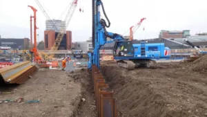
Cantilever walls are the simplest type, relying entirely on embedment for stability. They are used for moderate heights, typically up to 6-8 meters.
A cantilever sheet pile wall1 in sand with 5 meters exposed height is designed using the net pressure method2. The required embedment is found by iterating until the active moment equals the passive moment about the bottom. The maximum moment is then used to select the pile section.
](https://cnsteelplant.com/wp-content/uploads/2026/03/Article-Application-Port-3.webp)
Step-by-Step Cantilever Design
Given Data
- Exposed height (H): 5.0 m
- Soil: Sand, γ = 18 kN/m³
- Friction angle (φ): 35°
- Water table: Below embedment depth3
- Steel: ASTM A572 Grade 504 (345 MPa yield)
Step 1: Pressure Coefficients
Ka = tan²(45 – 35/2) = tan²(27.5) = 0.27
Kp = 1/Ka = 3.70
Step 2: Active Pressure at Dredge Line
pa = Ka × γ × H = 0.27 × 18 × 5 = 24.3 kPa
Step 3: Estimate Embedment Depth
Rule of thumb: D = 1.0 to 1.5 H = 5 to 7.5 m
Try D = 6.0 m
Step 4: Calculate Net Pressure Diagram
The net pressure is zero at the depth where active pressure equals passive pressure.
Find depth z0 below dredge line where pa = pp:
Ka × γ × (H + z0) = Kp × γ × z0
0.27 × (5 + z0) = 3.70 × z0
1.35 + 0.27z0 = 3.70z0
1.35 = 3.43z0
z0 = 0.39 m
Step 5: Calculate Forces
Active force above dredge line: F1 = 0.5 × 24.3 × 5 = 60.8 kN/m
Location of F1: 1/3 from bottom = 1.67 m above dredge line
Active force from dredge line to z0: F2 = 0.5 × 24.3 × 0.39 = 4.74 kN/m
Location of F2: 0.13 m above dredge line
Passive force below z0: F3 = 0.5 × (Kp × γ × D) × D = 0.5 × 3.70 × 18 × 6 × 6 = 1,199 kN/m (too high)
Iterate to find D that balances moments.
After iteration: D = 5.5 m
Step 6: Calculate Maximum Moment
Maximum moment occurs where shear is zero. For this wall, Mmax = 145 kN-m/m.
Step 7: Select Section
σallowable = 345 / 1.5 = 230 MPa = 230,000 kN/m²
S = 145,000 / 230,000 = 630 cm³/m
Selected: U 400 x 100-10.5 (S = 1,080 cm³/m)
Step 8: Total Length
Total = 5.0 + 5.5 = 10.5 m
Design Summary
- Pile type: U 400 x 100-10.5
- Steel grade: ASTM A572 Grade 504
- Total length: 10.5 m
- Embedment: 5.5 m
- Section modulus: 1,080 cm³/m (adequate)
My Experience
For a small coastal revetment with 4 m height, we used a cantilever design. The wall was in good sand, and the embedment was 4.5 m. The U 400 x 100 piles drove easily and have performed well for years.
Conclusion
Sheet pile design for coastal engineering requires careful selection of soil parameters, water levels, and loads. Use Excel for iterative calculations, reference design manuals for methods, and work through examples to verify your approach. Cantilever walls are suitable for moderate heights up to 6-8 meters.
-
Explore this link to understand the principles and applications of cantilever sheet pile walls in construction. ↩ ↩ ↩ ↩ ↩ ↩ ↩ ↩
-
Learn about the net pressure method, a crucial technique for ensuring stability in cantilever sheet pile designs. ↩ ↩ ↩ ↩ ↩ ↩ ↩
-
Find out how to accurately calculate embedment depth, essential for the stability of sheet pile walls. ↩ ↩ ↩ ↩
-
Discover the specifications and advantages of ASTM A572 Grade 50 steel, commonly used in structural applications. ↩ ↩ ↩ ↩ ↩