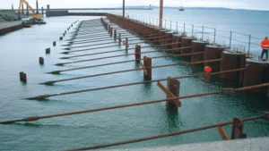
You are standing in a dense city center. A new metro line is being built underground. The station excavation is 15 meters deep. On one side is a hospital. On the other side is a historic building. The noise and vibration from traditional pile driving would cause unacceptable disruption.
Press-in sheet pile installation is the ideal method for metro projects1 in urban areas. It uses hydraulic jacks to press piles into the ground without impact or vibration. The method is nearly silent and produces no ground vibration, making it safe for adjacent structures. Press-in piling can install sheet piles in tight spaces with minimal headroom.
[^2] for metro station excavation](https://placehold.co/600x400 "Press-In Sheet Pile Installation")](https://cnsteelplant.com/wp-content/uploads/2026/03/Article-Application-Subway-1.webp)
I have supplied sheet piles for metro projects1 where press-in installation was required. A metro project in Singapore used press-in piling next to a historic mosque. A metro project in London used press-in piling under a low-clearance bridge. Let me walk you through how press-in installation works for metro projects1.
Sheet pile supplier
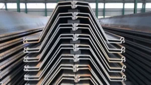
Choosing the right sheet pile supplier1 for metro projects is critical. The supplier must provide piles with consistent interlocks, tight tolerances, and reliable material properties.
A sheet pile supplier1 for metro projects should offer hot-rolled U-type or Z-type piles certified to EN 10248 or ASTM standards. The supplier should be able to provide piles in long lengths (15-25 m) with straightness tolerances suitable for press-in installation. Suppliers like ArcelorMittal (AZ series), Nucor (PZC series), and certified Chinese mills are common choices.
[^1] warehouse with steel piles](https://placehold.co/600x400 "Sheet Pile Supplier")](https://cnsteelplant.com/wp-content/uploads/2026/03/Article-Application-Subway-2.webp)
What to Look for in a Supplier
Let me explain the key factors to consider when selecting a sheet pile supplier1 for metro projects.
Product Requirements
| Requirement | Why It Matters |
|---|---|
| Hot-rolled sections | Consistent interlocks, better for press-in |
| EN 10248 or ASTM certification2 | Quality assurance |
| Tight straightness tolerance | Press-in requires straight piles |
| Long lengths (15-25 m) | Metro excavations are deep |
| Marine grade available | For groundwater corrosion |
Supplier Qualifications
| Qualification | What to Check |
|---|---|
| Mill certification | EN 10204 Type 3.1 or 3.2 |
| Previous metro projects | References from similar work |
| Stock availability | Lead time for delivery |
| Technical support | Engineering assistance |
Major Sheet Pile Suppliers
| Supplier | Product Line | Region |
|---|---|---|
| ArcelorMittal | AZ series (Z-type), PU series (U-type) | Global |
| Nucor Skyline | PZC, PZ series | North America |
| JFE Steel | U-type, Z-type | Asia |
| Chinese mills | EN 10248, ASTM sections | Asia, Middle East |
My Experience
For a metro project in Singapore, we supplied AZ 26 sheet piles from ArcelorMittal. The piles had tight straightness tolerance3s (1:500), which was essential for the press-in installation. The supplier provided mill certificates and technical support throughout the project.
Sheet pile shear capacity
Sheet pile shear capacity is the resistance of a pile to lateral forces that try to slide one section past another. In metro projects, shear capacity is important at splice locations and at the interface with walers.
Sheet pile shear capacity is determined by the interlock strength and the section’s web thickness. For U-type piles with Larssen interlocks, the shear capacity is typically 200-400 kN per meter of wall. For Z-type piles, the shear capacity is similar or higher. Splices must be designed to transfer the full shear force.
[^1] diagram](https://placehold.co/600x400 "Sheet Pile Shear Capacity")](https://cnsteelplant.com/wp-content/uploads/2026/03/Article-application-Cofferdam-Deep-Excavation-4.webp)
Shear Capacity Design
Let me explain how shear capacity is calculated and used in design.
Shear Capacity Components
| Component | Contribution |
|---|---|
| Interlock friction | Resists sliding between piles |
| Web thickness | Resists vertical shear in the pile |
| Splice connection | Transfers shear at splices |
Typical Shear Capacity Values
| Section | Shear Capacity (kN/m) | Notes |
|---|---|---|
| U 400 x 125-13 | 250-350 | Larssen interlock |
| U 400 x 170-15.5 | 300-400 | Thicker web |
| AZ 18 | 250-350 | Ball-and-socket interlock |
| AZ 26 | 300-400 | Thicker section |
Shear Check for Metro Walls
- Calculate maximum shear force from soil and water pressures
- Verify shear capacity > shear force
- Apply safety factor (typically 1.5)
Shear at Splices
- Splices must be designed for full shear capacity
- Full penetration butt welds with backup bars
- Shear transfer through weld and interlock
My Experience
For a metro project with 15 m excavation, the maximum shear force was 280 kN/m. We used AZ 26 piles with shear capacity of 350 kN/m, providing a 25% safety margin. The splices were designed with full penetration welds that were tested ultrasonically.
Waler SHEET pile
A waler1 is a horizontal beam that distributes bracing forces from sheet piles2 to struts or rakers. In metro projects, waler1s are essential for deep excavations.
A waler1 is a steel beam (typically H-beam or W-beam) attached to the sheet pile wall at brace levels. The waler1 transfers the soil and water pressure from the sheet piles2 to the struts or rakers. Walers are usually made from wide-flange sections (W 12×50, W 14×70) and are welded or bolted to the sheet piles2.
[^1] connection to sheet pile wall at metro excavation](https://placehold.co/600x400 "Waler Sheet Pile Connection")](https://cnsteelplant.com/wp-content/uploads/2026/03/Article-application-Cofferdam-Deep-Excavation-5.webp)
Waler Design and Installation
Let me explain the key aspects of waler1 design for metro projects.
Waler Functions
- Distributes bracing forces across multiple piles
- Prevents local bending of individual piles
- Transfers load from sheet piles2 to struts
- Provides connection point for bracing
Typical Waler Sections
| Excavation Depth | Typical Waler Section | Capacity |
|---|---|---|
| 5-8 m | W 12×50 | Moderate |
| 8-12 m | W 14×70 | Medium |
| 12-15 m | W 16×89 | High |
| 15-20 m | W 18×106 | Very high |
Waler Connection Details
- Welded to sheet piles2 (continuous or intermittent)
- Bolted to sheet piles2 through pre-drilled holes
- Supported by brackets or corbels on the piles
Waler Spacing
- Typically at 3-5 m vertical spacing
- Spacing determined by bending capacity of sheet piles2
- Closer spacing for deeper excavations
My Experience
For a metro station with 15 m excavation, we used three levels of waler1s:
- Level 1 (3 m depth): W 14×70
- Level 2 (7 m depth): W 16×89
- Level 3 (11 m depth): W 16×89
The waler1s were welded to the sheet piles2 at 1 m intervals. The struts were connected to the waler1s at 4 m horizontal spacing.
Sheet piling handbook design
Sheet piling handbooks provide comprehensive design guidance for engineers working on metro projects and other deep excavations.
The most useful sheet piling handbooks include the ArcelorMittal Sheet Piling Handbook1, the USACE Engineer Manual EM 1110-2-25042, and the USS Steel Sheet Piling Design Manual3. These handbooks cover earth pressure theory4, design methods, installation, and corrosion protection. They include worked examples and design charts for cantilever and anchored walls.
](https://cnsteelplant.com/wp-content/uploads/2026/03/Article-application-4.webp)
Comparison of Design Handbooks
Let me compare the most useful handbooks for metro projects.
ArcelorMittal Sheet Piling Handbook1
| Feature | Description |
|---|---|
| Latest edition | Updated regularly |
| Sections covered | PU, AZ series |
| Design methods | Limit state (Eurocode) and working stress |
| Worked examples | Yes, for various conditions |
| Availability | Free download from ArcelorMittal |
USACE Engineer Manual EM 1110-2-25042
| Feature | Description |
|---|---|
| Latest edition | 2020 (update to 1994 manual) |
| Sections covered | All types |
| Design methods | Working stress with safety factors |
| Worked examples | Yes, extensive |
| Availability | Free download from USACE |
USS Steel Sheet Piling Design Manual3
| Feature | Description |
|---|---|
| Latest edition | 1960s (out of print) |
| Sections covered | U-type, Z-type |
| Design methods | Working stress |
| Worked examples | Yes, classic examples |
| Availability | Used copies, PDF scans |
How to Use Handbooks for Metro Projects
| Design Step | Handbook Reference |
|---|---|
| Soil parameters | Chapter on earth pressure |
| Embedment depth | Design charts or worked examples |
| Bending moment | Calculation methods |
| Section selection | Section properties tables |
| Anchor design | Anchored wall chapter |
My Experience
For metro projects, I use a combination of handbooks. The ArcelorMittal handbook for section properties and modern design methods. The USACE manual for factor of safety guidance. The USS manual for classic worked examples and design charts.
Conclusion
Press-in sheet pile installation is the preferred method for metro projects in urban areas. It produces no vibration and minimal noise. Sheet piles must be supplied with tight tolerances for press-in installation. Walers distribute bracing forces. Design handbooks (ArcelorMittal, USACE, USS)1 provide comprehensive guidance for engineers.
-
Check this link for detailed design handbooks that offer essential guidance for engineers working with sheet piles. ↩ ↩ ↩ ↩ ↩ ↩ ↩ ↩ ↩ ↩ ↩ ↩ ↩ ↩ ↩ ↩ ↩
-
This resource offers extensive worked examples and safety factors crucial for effective design. ↩ ↩ ↩ ↩ ↩ ↩ ↩ ↩ ↩ ↩ ↩
-
Discover timeless design examples and insights from the USS manual that can enhance your project. ↩ ↩ ↩
-
Understanding this theory is essential for effective design; explore resources that explain its application. ↩