You are designing a new port terminal. The water is 15 meters deep, the ships are large, and the soil conditions are complex. The engineer asks: "How deep do we drive the sheet piles?" Getting this answer wrong can mean wall failure or wasted steel.
Sheet pile wall depth is calculated using limit equilibrium methods that balance active earth pressure from the retained side against passive resistance from the embedded side. The required embedment depth1 (D) is typically 0.5 to 0.8 times the exposed wall height (H) for anchored walls, and 1.0 to 1.5 times H for cantilever walls. Final depth is verified through iterative analysis.
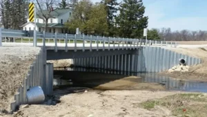
[^2] calculation diagram for port structure](https://placehold.co/600x400 "Sheet Pile Wall Depth Calculation")](https://cnsteelplant.com/wp-content/uploads/2026/03/Article-Application-Port-3-1.webp)
I have worked on port projects where getting the depth right was critical. A port in the UAE required 18-meter anchored walls with 9 meters embedment. A riverbank project in Southeast Asia used 6-meter cantilever walls with 7 meters embedment. Let me walk you through how engineers determine the right depth.
What is the rule of thumb for sheet pile depth?
Rules of thumb provide a starting point for estimating embedment depth1 before detailed analysis. They are useful for preliminary design and checking calculations.
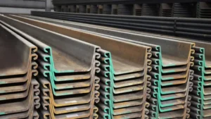
For cantilever sheet pile walls2, the rule of thumb is embedment depth1 (D) = 1.0 to 1.5 times the exposed wall height (H). For anchored sheet pile walls3, D = 0.5 to 0.8 times H. These ratios apply to typical soil conditions. Soft clays require deeper embedment; dense sands require less.
[^1]](https://placehold.co/600x400 "Sheet Pile Embedment Rule of Thumb")](https://cnsteelplant.com/wp-content/uploads/2026/03/Article-Application-Port-3.webp)
Understanding the Rules of Thumb
Let me explain where these rules come from.
Cantilever Walls
Cantilever walls rely entirely on the soil below the excavation to hold them in place. The wall rotates around a point near the bottom. The embedment must be deep enough to develop enough passive resistance to balance the active pressure above.
The rule D = 1.0 to 1.5 H comes from decades of experience. For example:
- H = 6 m → D = 6 to 9 m
- Total pile length = H + D = 12 to 15 m
Anchored Walls
Anchored walls have a tie rod or ground anchor that provides support at the top. This reduces the required embedment because the anchor takes some of the load. The wall behaves like a propped cantilever.
The rule D = 0.5 to 0.8 H is typical:
- H = 12 m → D = 6 to 10 m
- Total pile length = H + D = 18 to 22 m
Factors That Affect the Rule
| Factor | Effect on Embedment |
|---|---|
| Soft clay | Deeper embedment needed (use upper end of range) |
| Dense sand | Shallower embedment possible (use lower end) |
| Water table | Water reduces effective stress, deeper embedment needed |
| Surcharge loads | Additional loads require deeper embedment |
| Multiple anchors | More anchors allow shallower embedment |
Limitations of Rules of Thumb
Rules of thumb are not substitutes for analysis. They are useful for:
- Preliminary cost estimates
- Checking computer results for reasonableness
- Rough planning for equipment and materials
Always perform detailed analysis for final design.
My Experience
For the riverbank project (cantilever wall, H = 6 m, good sand), the rule suggested D = 6 to 9 m. The detailed analysis gave D = 7.2 m, right in the middle. For a port project (anchored wall, H = 18 m, dense sand), the rule suggested D = 9 to 14 m. The analysis gave D = 11 m.
What is the formula for pile depth?
The formula for pile depth is not a single equation but a series of calculations that balance forces and moments on the wall.
The pile depth is determined by solving for the embedment depth (D) that satisfies equilibrium: the sum of horizontal forces equals zero, and the sum of moments about any point equals zero. For cantilever walls, the solution is iterative. For anchored walls, the free earth support method provides a direct solution for the required depth.
](https://cnsteelplant.com/wp-content/uploads/2026/03/Article-Application-Port-2.webp)
The Free Earth Support Method1 (Anchored Walls)
Let me walk through the most common method for anchored walls.
Step 1: Calculate Active and Passive Pressures2
Active pressure at depth z: pa = Ka × γ × z + q × Ka – 2c√Ka
Passive pressure at depth z: pp = Kp × γ × z + q × Kp + 2c√Kp
For sand with no cohesion (c = 0) and no surcharge (q = 0):
pa = Ka × γ × z
pp = Kp × γ × z
Step 2: Determine the Location of Zero Shear
The maximum moment occurs where the shear force is zero. For anchored walls, this is between the anchor and the bottom.
Step 3: Calculate Anchor Force
The anchor force (T) is found by taking moments about the bottom:
T × (H + D – a) = (Active pressure moment) – (Passive pressure moment)
Where a is the anchor depth below the top.
Step 4: Solve for D
The embedment depth D must satisfy horizontal equilibrium:
Active force = Passive force + T
This gives an equation that can be solved for D.
Step 5: Apply Factor of Safety3
In practice, a factor of safety (typically 1.5 to 2.0) is applied to the passive resistance. This increases the required D.
Simplified Formula for Anchored Walls in Uniform Sand
A simplified formula can be used for preliminary design:
D = (Ka × H) / (Kp – Ka) × (some factor)
But this is too simplified for final design. The actual D is determined through the full equilibrium calculation.
For Cantilever Walls4
For cantilever walls, the depth is found by solving:
(Active pressure moment) = (Passive pressure moment) about the point of rotation
This is an iterative process because the point of rotation is not known in advance.
My Experience
For the port project, we used the free earth support method with a factor of safety of 1.5 on passive resistance. The calculation gave D = 10.8 m, and we specified 11 m.
What is the maximum depth of sheet piles1?
The maximum depth of sheet piles1 depends on the section modulus, steel grade, soil conditions, and bracing system.
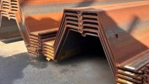
For cantilever walls, the practical maximum depth is about 8 meters in good soil. For anchored walls with a single anchor, depths up to 15 meters are common. With multiple anchors, depths can reach 20 to 25 meters. For combination walls (H-piles with sheet piles), depths over 30 meters are possible.
](https://cnsteelplant.com/wp-content/uploads/2026/03/Article-Application-Port-1.webp)
Factors Limiting Sheet Pile Depth
Let me explain what limits how deep sheet piles can go.
Section Modulus
The sheet pile section must have enough bending strength to resist the moment. As depth increases, the bending moment increases with the cube of the height. Very deep walls require very high section moduli.
| Wall Height | Typical Required S (cm³/m) | Possible Section |
|---|---|---|
| 6 m | 1,500 | U 400 x 125 |
| 10 m | 3,000 | U 600 x 180 or AZ 30 |
| 15 m | 5,000 | U 600 x 210 or AZ 50 |
| 20 m | 8,000 | Combination wall (H-pile + sheet) |
Embedment Requirements
For cantilever walls, the embedment depth must be at least as deep as the exposed height. A 10 m cantilever wall would need 10-15 m embedment, total pile length 20-25 m. This is often not practical.
Driving Limitations
Piles longer than 30 meters are difficult to handle and drive. They require very long leads on cranes, or they must be spliced in the field. Splicing adds cost and creates potential weak points.
Soil Conditions
Very deep piles may need to penetrate hard layers or rock. Driving through dense soil or cobbles becomes progressively harder as depth increases.
Maximum Depths Achieved
| Wall Type | Maximum Depth | Examples |
|---|---|---|
| Cantilever | 8 m | River banks, shallow excavations |
| Single anchor | 15 m | Port quay walls, deep excavations |
| Multi-anchor | 20-25 m | Deep water ports, metro stations |
| Combination | 30-40 m | Offshore platforms, very deep water |
My Experience
The deepest sheet pile wall I have worked on was 22 meters (exposed height) with two levels of anchors. We used AZ 50 piles and had to pre-drill through a dense sand layer. The total pile length was 32 meters, requiring splicing in the field.
How to determine embedment depth?
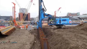
Embedment depth is determined through geotechnical analysis that balances active and passive pressures1. The process involves soil investigation2, pressure calculations, and iterative equilibrium.
The embedment depth is determined by: 1) conducting a soil investigation2 to get soil properties, 2) calculating active and passive pressures1 using Rankine or Coulomb theory, 3) iterating to find the depth that satisfies equilibrium, and 4) applying factors of safety to account for uncertainties.
](https://cnsteelplant.com/wp-content/uploads/2026/03/Article-Application-Port-4.webp)
Step-by-Step Process for Determining Embedment
Let me walk you through the full process.
Step 1: Site Investigation
- Drill boreholes to sufficient depth (typically 2 to 3 times the wall height)
- Collect soil samples at regular intervals
- Perform laboratory tests to determine:
- Soil type and layering
- Unit weight (γ)
- Friction angle (φ)
- Cohesion (c)
- Water table location
Step 2: Select Design Method
- Cantilever walls: Use net pressure method or beam-on-elastic-foundation
- Anchored walls: Use free earth support or fixed earth support method
- Complex conditions: Use finite element or finite difference software
Step 3: Calculate Active and Passive Pressures
For each soil layer, calculate:
- Active pressure coefficient: Ka = tan²(45 – φ/2)
- Passive pressure coefficient: Kp = tan²(45 + φ/2)
For cohesive soils, include cohesion terms.
Step 4: Assume an Embedment Depth
Start with an initial estimate based on rules of thumb:
- Cantilever: D = 1.0 to 1.5 H
- Anchored: D = 0.5 to 0.8 H
Step 5: Calculate Forces and Moments
- Compute active force and its location
- Compute passive force and its location
- For anchored walls, compute anchor force
- Check horizontal equilibrium
- Check moment equilibrium
Step 6: Iterate
If equilibrium is not satisfied, adjust D and repeat until convergence.
Step 7: Apply Factor of Safety
- Reduce passive resistance by a factor of safety3 (typically 1.5 to 2.0)
- Or increase active pressure by a factor
- The factor of safety3 increases the required D
Step 8: Verify with Software
- Run beam-on-elastic-foundation analysis
- Check deflections and bending moments
- Adjust if needed
Step 9: Finalize Depth
- Add corrosion allowance if needed
- Specify pile length as H + D
Factor of Safety Guide
| Application | FS on Passive | FS on Active |
|---|---|---|
| Temporary walls | 1.5 | 1.0 |
| Permanent walls | 2.0 | 1.0 |
| Marine structures | 2.0 | 1.0 |
| Seismic conditions | 1.5 | 1.0 |
My Experience
For the port project, we followed this process exactly. The soil investigation2 showed dense sand with some clay layers. We used the free earth support method with FS = 2.0 on passive resistance. The analysis gave D = 10.8 m, and we specified 11 m. The wall has performed well for over a decade.
Conclusion
Sheet pile wall depth1 is calculated by balancing active and passive earth pressures. For anchored walls, embedment is typically 0.5 to 0.8 times the exposed height. For cantilever walls, embedment is 1.0 to 1.5 times the exposed height. Always verify with detailed geotechnical analysis2.
-
Understanding the calculation of sheet pile wall depth is crucial for effective construction and stability. ↩ ↩ ↩ ↩ ↩ ↩ ↩ ↩ ↩
-
Exploring geotechnical analysis will enhance your knowledge of soil behavior and its impact on structural integrity. ↩ ↩ ↩ ↩ ↩ ↩
-
Exploring the factor of safety will help you understand how uncertainties are managed in engineering designs. ↩ ↩ ↩ ↩
-
Delve into the design of Cantilever Walls, a key aspect of structural engineering, to grasp their unique challenges and solutions. ↩