You are an engineer with a project that needs a retaining wall. The soil report is on your desk, and you need to design a sheet pile wall1 that is safe, economical, and constructible.
Steel sheet pile design follows established geotechnical principles. The wall must resist active soil pressure from the retained side and develop passive resistance from the embedded portion. For cantilever walls, embedment depth controls stability. For anchored walls2, tie rods or ground anchors reduce the required embedment and bending moment.
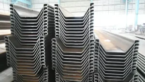
[^1] design drawings](https://placehold.co/600x400 "Sheet Pile Wall Design")](https://cnsteelplant.com/wp-content/uploads/2026/03/Article-application-2-2.webp)
I have worked with engineers on retaining wall projects around the world. The riverbank project in Southeast Asia was a classic cantilever wall design. A port project in the Middle East used anchored walls2 for deep water. Let me walk you through the design principles that apply to both.
Steel sheet pile design example
A design example helps make the principles concrete. Let me walk through a simplified cantilever wall design.
Consider a cantilever sheet pile wall1 retaining 6 meters of soil. The soil is sand with a unit weight of 18 kN/m³ and a friction angle of 32 degrees. We need to determine the required embedment depth2 and select a pile section.
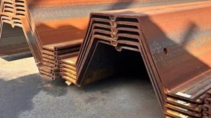
[^1] with dimensions](https://placehold.co/600x400 "Cantilever Sheet Pile Wall Design")](https://cnsteelplant.com/wp-content/uploads/2026/03/Article-Application-River-Embankment-3.webp)
Step-by-Step Design Calculation
Let me break this down into the steps a geotechnical engineer follows.
Step 1: Determine Soil Pressures
Active earth pressure coefficient (Ka) for sand: Ka = tan²(45 – φ/2)
For φ = 32°, Ka = tan²(45 – 16) = tan²(29) = 0.307
Passive earth pressure coefficient (Kp): Kp = 1/Ka = 3.25
The active pressure at the bottom of the excavation (6m depth):
Pa = Ka × γ × H = 0.307 × 18 × 6 = 33.2 kPa
Step 2: Estimate Embedment Depth
For cantilever walls, a rule of thumb is embedment (D) = H to 1.5H in good soil.
For this example, try D = 7 m (slightly more than H).
The actual required depth is found by balancing moments around the point of rotation. This is an iterative process.
Step 3: Calculate Bending Moment
The maximum bending moment3 occurs where the shear force is zero. For a cantilever wall in sand, this is roughly at 0.6 to 0.7 times the total wall height.
For our example, the maximum moment is approximately:
Mmax = (Ka × γ × H³) / 6 for a simplified analysis
Mmax = (0.307 × 18 × 6³) / 6 = (0.307 × 18 × 216) / 6 = 199 kN-m per meter of wall
Step 4: Select Pile Section
We need a section with a section modulus4 (S) that satisfies:
S ≥ Mmax / σallowable
For ASTM A328 steel, yield strength = 240 MPa. Using a safety factor of 1.5:
σallowable = 240 / 1.5 = 160 MPa = 160,000 kN/m²
Required S = 199 / 160,000 = 0.00124 m³/m = 1,240 cm³/m
From manufacturer data, a U-type pile like the 400×125 section has a section modulus4 of about 1,500 cm³/m, which works.
Step 5: Check Embedment
The actual embedment is verified by ensuring the passive resistance exceeds the active pressure. For this example, 7 m embedment is sufficient based on more detailed analysis.
Result:
Use U-type 400×125 sheet piles with 6 m exposed height and 7 m embedment. Total pile length = 13 m.
Sheet pile design example pdf
Many engineers look for PDF resources to guide their design work. Several excellent references are available.
The best resources for sheet pile design examples include the US Army Corps of Engineers Engineer Manual EM 1110-2-2504, Pile Buck’s Steel Sheet Piling Design Manual, and various university geotechnical engineering course materials. These provide step-by-step worked examples for both cantilever and anchored walls.
](https://cnsteelplant.com/wp-content/uploads/2026/03/Article-Application-Subway-1.webp)
Where to Find Reliable Design Examples
Let me share the resources I have used and recommended to engineers.
US Army Corps of Engineers EM 1110-2-25041
This manual is the gold standard for sheet pile design. It covers:
- Cantilever wall design with worked examples
- Anchored wall design with multiple anchor levels
- Design for seismic conditions
- Corrosion considerations
- Available free online
Pile Buck Steel Sheet Piling Design Manual2
This industry reference has been used for decades. It includes:
- Comprehensive design examples
- Properties for all common pile sections
- Installation guidance
- Updated editions available for purchase
University Course Materials3
Many geotechnical engineering courses make their materials available. Look for:
- MIT OpenCourseWare: Geotechnical engineering materials
- University of Washington: Foundation design notes
- Colorado State University: Retaining wall design
Software Resources
While hand calculations are essential for understanding, many engineers use software:
- DeepEX4: Specialized for sheet pile and retaining wall design
- GeoStudio: Comprehensive geotechnical software
- SPW 911: Sheet pile wall design software
What to Look For in a Good Design Example
A useful design example should include:
- Clear soil parameters and assumptions
- Step-by-step calculation of active and passive pressures
- Determination of embedment depth (for cantilever walls)
- Determination of anchor forces (for anchored walls)
- Calculation of bending moment and section selection
- Check of structural adequacy
- Consideration of water pressures if present
My Experience
When I work with engineers who are new to sheet pile design, I often point them to the USACE manual. The worked examples are clear and follow standard practice. The riverbank project in Southeast Asia was designed using methods from that manual, and the wall has performed perfectly.
Cantilever sheet pile wall1 design example pdf
Cantilever walls are the simplest type—no anchors, just a wall embedded in the ground. They are used for moderate heights.
A cantilever sheet pile wall relies entirely on the soil below the excavation to hold it in place. For a 6-meter wall in sand, the embedment depth is typically 6 to 9 meters. The design involves balancing active pressure from the retained side with passive pressure from the embedded side.
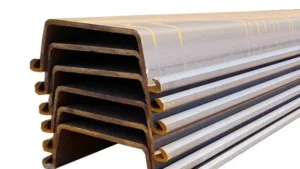
](https://cnsteelplant.com/wp-content/uploads/2026/03/Article-Application-Port-2.webp)
Detailed Cantilever Design Example
Let me walk through a more complete cantilever design.
Given Data:
- Wall height (H) = 6 m
- Soil: Sand, γ = 18 kN/m³, φ = 32°
- Water table: Below embedment depth
- Steel: ASTM A328, yield strength = 240 MPa
Step 1: Calculate Earth Pressure Coefficients
Ka = tan²(45 – 32/2) = tan²(29) = 0.307
Kp = 1/Ka = 3.25
Step 2: Determine Embedment Depth by Trial
We need to find D such that the sum of moments about the bottom of the wall is zero.
The active pressure acts over height (H + D). The passive pressure acts over depth D.
For sand, the pressure distributions are triangular. The net pressure diagram is more complex because the passive side has different coefficients.
Using the net pressure method, we assume the wall rotates about a point near the bottom. The active pressure is reduced by the passive pressure on the front side above the point of rotation.
After iterations, D = 7.2 m satisfies equilibrium.
Step 3: Calculate Maximum Bending Moment2
The maximum moment occurs where shear is zero. For this wall, that is at about 5.5 m below the top.
The moment at that point is computed by integrating the pressure diagram. For this example:
Mmax = 210 kN-m/m
Step 4: Select Section
Required section modulus: S = Mmax / σallowable
σallowable = 240 MPa / 1.5 = 160 MPa
S = 210 / 160,000 = 0.00131 m³/m = 1,310 cm³/m
Select U-type 400×125 (S = 1,500 cm³/m) or Z-type section with equivalent or greater modulus.
Step 5: Total Length
Total pile length = H + D = 6.0 + 7.2 = 13.2 m
Design Summary:
- Pile type: U-type 400×125
- Steel grade: ASTM A328
- Total length: 13.2 m
- Embedment: 7.2 m
- Section modulus3 provided: 1,500 cm³/m (adequate)
Limitations:
Cantilever walls are typically limited to heights of 6-8 meters in good soil. For taller walls, anchored walls are more economical.
Anchored sheet pile wall design example pdf
Anchored walls allow taller walls and reduce the required embedment depth1. A single anchor at the top is common for heights up to about 12 meters.
For an anchored wall, the anchor provides a reaction at the top, reducing the bending moment in the wall and allowing shallower embedment. For a 9-meter wall in sand, a single anchor at 1.5 m below the top reduces the required embedment from about 10 meters to about 5 meters.
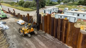
](https://cnsteelplant.com/wp-content/uploads/2026/03/Article-Application-City-3.webp)
Detailed Anchored Wall Design Example
Let me walk through a design for a taller wall.
Given Data:
- Wall height (H) = 9 m
- Soil: Sand, γ = 18 kN/m³, φ = 32°
- Anchor location: 1.5 m below top
- Anchor spacing: 3 m center to center
- Steel: ASTM A572 Grade 50, yield strength = 345 MPa
Step 1: Earth Pressure Coefficients
Ka = 0.307, Kp = 3.25 (same as previous example)
Step 2: Determine Embedment Depth
With an anchor, the embedment depth1 can be reduced. For a 9 m wall, embedment of 5.0 m is often sufficient.
Using the free earth support method, we assume the wall is supported at the anchor and at the bottom by passive pressure. The required depth is found by taking moments about the anchor.
After calculation, D = 5.2 m satisfies equilibrium.
Step 3: Calculate Anchor Force
The anchor force2 is determined from horizontal equilibrium. For this example:
T = 85 kN per meter of wall
For anchors at 3 m spacing, each anchor carries 255 kN.
Step 4: Calculate Maximum Bending Moment
The maximum moment occurs between the anchor and the bottom. For this wall, Mmax = 180 kN-m/m—lower than the cantilever wall despite the taller height.
Step 5: Select Section
Required section modulus: S = Mmax / σallowable
σallowable = 345 MPa / 1.5 = 230 MPa
S = 180 / 230,000 = 0.00078 m³/m = 780 cm³/m
A Z-type section3 like AZ 13 (S = 1,300 cm³/m) is more than adequate. The Z section is chosen for efficiency.
Step 6: Anchor Design
Each anchor must resist 255 kN. The anchor could be:
- A driven steel pile (raked pile) with tie rod
- A grouted ground anchor4
- A deadman anchor
For this example, a grouted ground anchor4 with a 150 mm diameter and 10 m length is suitable.
Design Summary:
- Pile type: Z-type AZ 13
- Steel grade: ASTM A572 Grade 50
- Total length: 9.0 + 5.2 = 14.2 m
- Embedment: 5.2 m
- Anchor: Grouted ground anchor, 150 mm diameter, 10 m length, 255 kN capacity
- Anchor spacing: 3 m
Advantages of Anchored Wall:
- Taller wall (9 m vs 6 m for cantilever)
- Shallower embedment (5.2 m vs 7.2 m)
- Lower bending moment (180 vs 210 kN-m/m)
- More economical for taller heights
My Experience
For the port project in the Middle East, we used anchored walls5 with two levels of anchors. The wall height was 18 m, and the anchors were essential to control bending moments. Each anchor was a driven steel pile with a tie rod connected to the sheet pile wall. The design followed the same principles as this example, scaled up for the larger loads.
Conclusion
Sheet pile wall design1 balances active and passive earth pressures. Cantilever walls2 work for moderate heights. Anchored walls allow taller walls and reduce embedment depth. Always verify designs with site-specific soil parameters.
-
Understanding sheet pile wall design is crucial for effective construction and soil management, ensuring stability and safety. ↩ ↩ ↩ ↩ ↩ ↩ ↩
-
Exploring cantilever walls will provide insights into their applications and benefits in managing earth pressures. ↩ ↩ ↩ ↩ ↩ ↩ ↩
-
Find out why Z-type sections are preferred in construction for their efficiency and strength. ↩ ↩ ↩ ↩
-
Gain insights into grouted ground anchors, their design, and their application in enhancing wall stability. ↩ ↩ ↩ ↩ ↩
-
Explore the advantages of anchored walls, including their ability to support taller structures and reduce embedment depth. ↩