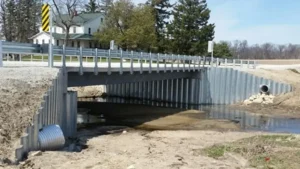
You are designing a marine structure—a port, a seawall, or a coastal protection system. The environment is harsh: saltwater, waves, tides, and often soft soils. Choosing the wrong sheet pile can lead to corrosion failure, instability, or construction delays.
Sheet pile selection for marine projects requires consideration of water depth, soil conditions, corrosion environment, wave loads, and installation methods. The US Army Corps of Engineers Engineer Manual EM 1110-2-25041 provides comprehensive guidelines, including embedment rules, design calculations, and worked examples for marine structures.
](https://cnsteelplant.com/wp-content/uploads/2026/03/Article-Application-Port-3-1.webp)
I have worked on marine projects across the Middle East, Southeast Asia, and Africa. The USACE manual has been my primary reference. A port project in the UAE followed the manual’s guidelines for anchored walls in sand. A coastal protection project in Southeast Asia used the corrosion guidance to select ASTM A690 steel. Let me walk you through the key engineering guidelines for marine sheet pile selection.
Sheet pile embedment depth1 rule of thumb
The embedment depth1 rule of thumb provides a quick estimate for preliminary design. For marine projects, water depth and wave action2 increase the required embedment.
For anchored sheet pile walls in marine environments, the rule of thumb is embedment depth1 (D) = 0.6 to 0.9 times the exposed height (H). For cantilever walls, D = 1.2 to 1.8 times H. Soft soils and high wave loads require deeper embedment; dense sands allow shallower embedment.
[^1] rule of thumb for marine projects](https://placehold.co/600x400 "Marine Sheet Pile Embedment Rule")](https://cnsteelplant.com/wp-content/uploads/2026/03/Article-Application-Port-4.webp)
Marine-Specific Embedment Factors
Let me explain how marine conditions affect the rule.
Water Depth Factor
For marine walls, the exposed height includes the water depth plus any additional height above water. A wall with 10 m water depth and 2 m above water has H = 12 m.
Wave Load Factor
Waves add dynamic loads that increase the required embedment. For locations with significant wave action2, increase embedment by 10-20%.
Soil Type Factor
| Soil Type | Cantilever D/H | Anchored D/H |
|---|---|---|
| Dense sand | 1.2 – 1.5 | 0.6 – 0.7 |
| Loose sand | 1.4 – 1.7 | 0.7 – 0.8 |
| Stiff clay | 1.5 – 1.8 | 0.7 – 0.9 |
| Soft clay | 1.8 – 2.2 | 0.8 – 1.0 |
Wave Action Factor
- Sheltered waters (harbors, marinas): No additional factor
- Moderate wave action2: Add 10% to D
- Exposed coastlines, high waves: Add 15-20% to D
Example Calculation
Given:
- Water depth: 10 m
- Freeboard: 2 m
- H = 12 m
- Soil: Dense sand
- Wave action: Moderate
Base anchored D/H = 0.65
D = 0.65 × 12 = 7.8 m
Wave factor: 1.10
Final D = 7.8 × 1.10 = 8.6 m
My Experience
For the port project in the UAE, we had H = 18 m, dense sand, and moderate wave action2. The rule suggested D = 0.65 × 18 × 1.10 = 12.9 m. The final design used D = 11 m after detailed analysis. The rule was conservative but provided a good starting point.
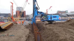
Sheet pile design calculation
Sheet pile design calculation for marine projects1 follows limit equilibrium methods, with additional considerations for wave loads, tidal variations, and corrosion allowance2.
The design calculation involves determining active and passive earth pressures, calculating the required embedment depth3, determining anchor forces (for anchored walls), calculating bending moments4, selecting the pile section, and adding corrosion allowance2. Water pressure from tides and wave loads are included in the pressure calculations.
](https://cnsteelplant.com/wp-content/uploads/2026/03/Article-Application-Port-3.webp)
Step-by-Step Marine Design Calculation
Let me walk through the calculation process for a marine anchored wall.
Step 1: Determine Design Conditions
- Water depth at mean high water (MHW): 12 m
- Water depth at mean low water (MLW): 8 m
- Design water level: MHW + storm surge (13.5 m)
- Wave height: 2.5 m
- Soil properties: Sand, γ = 18 kN/m³, φ = 32°
Step 2: Calculate Earth Pressure Coefficients
Ka = tan²(45 – φ/2) = 0.307
Kp = 1/Ka = 3.255
Step 3: Include Water Pressure
Water pressure at dredge line:
pw = γw × (design water depth) = 10 × 13.5 = 135 kPa
Step 4: Include Wave Pressure
Wave pressure at the wall face:
pwav = γw × Hw × factor = 10 × 2.5 × 1.0 = 25 kPa (approximate)
Step 5: Calculate Active Pressure
At dredge line:
pa = Ka × γ’ × H + pw + pwav
γ’ = submerged unit weight = 10 kN/m³
pa = 0.307 × 10 × 12 + 135 + 25 = 36.8 + 135 + 25 = 196.8 kPa
Step 6: Calculate Passive Pressure (below dredge line)
pp = Kp × γ’ × z
Step 7: Determine Embedment by Iteration
Solve for D such that moments balance. For this example, D = 9.5 m.
Step 8: Calculate Anchor Force
Anchor force T = 320 kN/m at anchor depth 2.5 m below top.
Step 9: Calculate Bending Moment
Maximum moment Mmax = 480 kN-m/m
Step 10: Select Pile Section
σallowable = 345 / 1.5 = 230 MPa for A572 Gr50
S = 480,000 / 230,000 = 2,087 cm³/m
Select AZ 26 (S = 2,600 cm³/m)
Step 11: Add Corrosion Allowance
Marine corrosion allowance2: 2 mm over 50 years
Add to section thickness
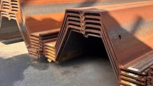
Steel sheet pile design example
A worked design example from the USACE manual illustrates the complete design process for a marine sheet pile wall.
Consider an anchored sheet pile wall for a harbor with 10 m water depth. Soil is sand with φ = 35°, γ = 18 kN/m³. The wall is anchored with tie rods at 2 m below top. The example walks through the free earth support method, determining embedment depth, anchor force, and required section modulus.
](https://cnsteelplant.com/wp-content/uploads/2026/03/Article-Application-Port-2.webp)
Detailed Design Example (Based on USACE Methods)
Project Data
- Water depth: 10 m
- Freeboard: 2 m
- Total wall height (H): 12 m
- Anchor depth (a): 2 m below top
- Soil: Sand, γ = 18 kN/m³ (above water), γsub = 10 kN/m³
- Friction angle (φ): 35°
- Steel: ASTM A572 Grade 501 (345 MPa yield)
- Factor of safety: 1.5 on passive resistance2
Step 1: Earth Pressure Coefficients
Ka = tan²(45 – 35/2) = tan²(27.5) = 0.27
Kp = 1/Ka = 3.70
Step 2: Active Pressure at Dredge Line3
pa = Ka × γsub × H + γw × H
pa = 0.27 × 10 × 10 + 10 × 10 = 27 + 100 = 127 kPa
Step 3: Estimate Embedment Depth
Rule of thumb: D = 0.6 to 0.8 H = 7.2 to 9.6 m
Try D = 8.0 m
Step 4: Calculate Active Force
Active force above dredge line: F1 = 0.5 × 127 × 10 = 635 kN/m
Location from dredge line: 10/3 = 3.33 m
Step 5: Calculate Passive Force
Passive force below dredge line: Fp = 0.5 × Kp × γsub × D²
Fp = 0.5 × 3.70 × 10 × 8² = 1,184 kN/m
Step 6: Apply Factor of Safety
Reduced passive force = Fp / 1.5 = 789 kN/m
Step 7: Calculate Anchor Force
Sum moments about anchor:
T × (H – a) + Fp × (D/3) = F1 × (H – a + H/3)
Solve for T = 210 kN/m
Step 8: Check Horizontal Equilibrium
Active force = 635 kN/m
Passive force (reduced) + T = 789 + 210 = 999 kN/m > 635 OK
Step 9: Calculate Maximum Moment
Maximum moment occurs where shear = 04. For this wall, Mmax = 380 kN-m/m
Step 10: Select Section
σallowable = 345 / 1.5 = 230 MPa = 230,000 kN/m²
S = 380,000 / 230,000 = 1,650 cm³/m
Select AZ 18 (S = 1,800 cm³/m) or U 400 x 125-13 (S = 1,590)
Step 11: Total Length
Total = H + D = 12 + 8 = 20 m
Design Summary
- Section: AZ 18 (or equivalent)
- Total length: 20 m
- Embedment: 8 m
- Anchor: Tie rods at 2 m, 3 m spacing, 630 kN each
- Steel grade: ASTM A572 Grade 50 or ASTM A690 for marine
USACE sheet pile Design manual
The US Army Corps of Engineers Engineer Manual EM 1110-2-2504 is the authoritative reference for sheet pile design, especially for marine and coastal projects.
USACE EM 1110-2-25041, "Design of Sheet Pile Walls," provides comprehensive guidance on earth pressure theory2, design methods, seismic analysis, corrosion protection, and installation. The manual includes worked examples for cantilever walls, anchored walls, and cellular cofferdams, with specific considerations for marine environments.
](https://cnsteelplant.com/wp-content/uploads/2026/03/Article-Application-Port-1.webp)
Key Sections of the USACE Manual
Let me summarize the most important sections for marine projects.
Chapter 1: Introduction
- Scope and applicability
- Design philosophy
- Safety factors
Chapter 2: Site Characterization
- Soil investigation requirements
- Soil properties for marine sites
- Water level determination (tides, storm surge)
- Wave loads
Chapter 3: Earth Pressure Theory
- Rankine and Coulomb theories
- Water pressure effects
- Surcharge loads
- Seismic earth pressure
Chapter 4: Cantilever Walls
- Design methods
- Embedment determination
- Bending moment calculation
- Worked examples
Chapter 5: Anchored Walls
- Free earth support method
- Fixed earth support method
- Anchor design
- Tie rod design
- Worked examples
Chapter 6: Cellular Cofferdams
- Design of circular and diaphragm cells
- Interlock stresses
- Filling materials
Chapter 7: Seismic Design
- Pseudostatic analysis
- Seismic earth pressure coefficients
- Liquefaction considerations
Chapter 8: Corrosion and Durability
- Marine corrosion mechanisms
- Corrosion allowance
- Cathodic protection
- Coatings
Chapter 9: Installation
- Driving equipment
- Guide frames
- Interlock care
Marine-Specific Guidance in USACE Manual
- Tidal water level variations
- Storm surge conditions
- Wave pressure calculations
- Marine corrosion rates
- Sacrificial anodes for cathodic protection
How to Use the USACE Manual for Marine Projects
| Step | Action |
|---|---|
| 1 | Determine site conditions (water depth, tide, waves, soil) |
| 2 | Select design water level (MHW + storm surge) |
| 3 | Calculate wave pressures using Chapter 3 methods |
| 4 | Determine earth pressures with water and wave loads |
| 5 | Follow Chapter 4 or 5 design procedures |
| 6 | Apply corrosion allowance from Chapter 8 |
| 7 | Verify installation methods from Chapter 9 |
My Experience
For the port project in the UAE, we used the USACE manual extensively. The manual’s guidance on tidal variations and storm surge was critical for determining the design water level. The corrosion chapter helped us select ASTM A690 steel and design the cathodic protection system.
Conclusion
Engineering guidelines for marine sheet pile selection1 start with the USACE manual. Use embedment rules as a starting point, perform detailed calculations with wave and tidal loads, and add corrosion allowance2 for long-term durability.
-
Explore this link to understand the latest techniques and guidelines for selecting marine sheet piles effectively. ↩ ↩ ↩ ↩ ↩ ↩ ↩ ↩
-
This resource will provide insights into calculating corrosion allowance, ensuring the longevity of marine structures. ↩ ↩ ↩ ↩ ↩ ↩ ↩ ↩ ↩ ↩
-
Learning how to calculate active pressure at the dredge line can enhance your design accuracy for marine structures. ↩ ↩
-
Understanding maximum moment is essential for designing safe and effective structures, especially in marine environments. ↩ ↩