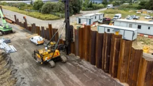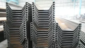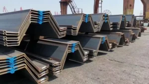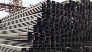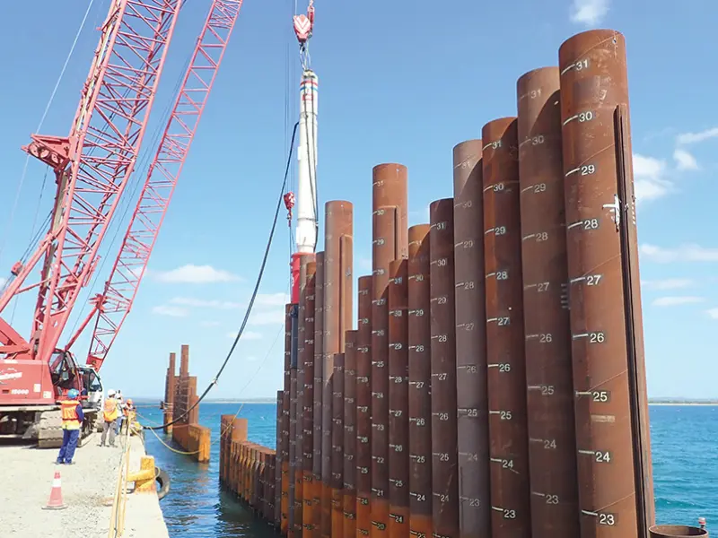
A sheet pile wall can fail long before the steel fails. I have seen good steel perform badly because the wall depth, load path, and corrosion allowance were not designed as one system.
To design a steel sheet pile wall, I start with soil and water pressures, required excavation depth, surcharge loads, and service life. Then I choose the wall type, calculate embedment depth, check bending and deflection, decide whether a capping beam is needed, and allow for corrosion or reinforcement where load transfer demands it.
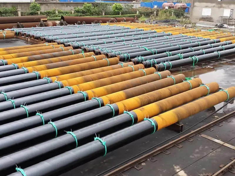
When I discuss sheet pile wall design with contractors or distributors, I do not begin with the pile section. I begin with the job condition. A wall beside a river, a basement excavation in a city, and a port retaining wall can all use steel sheet piles, but they should not be designed in the same way. In my experience, the best design work comes from treating the wall as a full system: soil, water, steel section, installation method, top connection, and long-term durability all need to fit together.
How deep do sheet piles need to go?
If the wall is too shallow, it may move, rotate, or lose toe resistance. Many problems in sheet pile work start below ground, not above it.
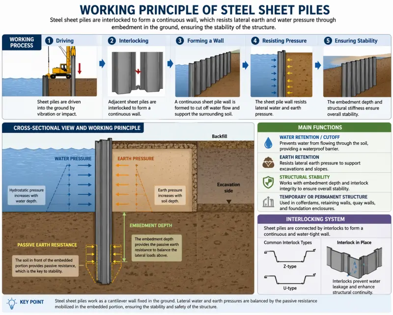
Sheet piles need to go deep enough to resist earth pressure, water pressure, and uplift while providing passive resistance below the excavation line. In practice, embedment depth often falls around 30% to 70% of the exposed wall height, but the real value must come from geotechnical design, not a simple rule alone.
I never design embedment from a single rule
I understand why people ask for a quick rule. On many jobs, the first question is, “How deep should the sheet piles go?” A rule of thumb is useful for early budgeting, but I do not like using it as the final answer. Embedment depth is one of the most important parts of the wall design because it controls stability, bending moment distribution, and wall deflection.
In a simple cantilever wall, the embedded portion of the sheet pile works by mobilizing passive soil resistance in front of the toe. In an anchored wall, embedment still matters because the toe must provide stability and help control movement. If I underestimate the embedment, the wall can rotate more than expected, anchor loads can rise, and the bending moment can shift to a location that was not assumed in the first design pass.
What controls sheet pile embedment depth?
I usually look at embedment as the result of six design inputs:
1. Excavation height or retained height
The taller the exposed wall, the larger the lateral earth pressure. That usually means deeper embedment.
2. Soil strength below dredge or excavation level
Passive resistance depends heavily on the soil in front of the embedded toe. Dense sand and stiff clay behave very differently from soft fill or loose silt.
3. Groundwater and hydraulic difference
If there is water on one side of the wall, or different water levels across the wall, hydrostatic pressure can increase the required depth.
4. Wall support system
A cantilever wall usually needs more embedment than a braced or anchored wall because the wall toe must do more of the stabilizing work.
5. Surcharge loads
Traffic, stored materials, cranes, nearby buildings, and temporary construction loads all add pressure behind the wall.
6. Movement limits
A wall in an open site may tolerate more movement than a wall next to utilities, rail lines, or existing structures. If movement must be small, I may increase embedment even if the minimum stability check already passes.
A practical way I explain embedment to buyers
When I speak with a contractor who is still pricing a job, I usually separate the question into “budget depth” and “design depth.”
| Stage | What I use it for | Typical approach |
|---|---|---|
| Budget estimate | Early quotation or supplier discussion | Use a rule-of-thumb range based on wall height and wall type |
| Preliminary design | Early engineering review | Add soil profile, water level, and surcharge assumptions |
| Final design | Construction issue design | Calculate earth pressures, passive resistance, bending moment, and serviceability checks |
A common early estimate is that embedment may be around one-third to two-thirds of the retained height, depending on wall type and support condition. I treat that as a conversation starter only. Final embedment should be checked by geotechnical design methods such as limit equilibrium or soil-structure interaction approaches. ArcelorMittal’s engineering guidance also emphasizes that sheet pile walls should be designed from geotechnical and structural checks rather than by a single blanket rule.
My own view on embedment in real projects
My own view is simple: if the soil report is weak, I become conservative about embedment before I become aggressive about steel grade. I would rather add reasonable toe depth early than chase wall movement later with expensive site fixes. On riverbank and flood-control work, I have seen that the contractor cares most about installation speed, but the owner cares most about long-term stability. Embedment is where those two goals meet. If I get that part right, the rest of the wall design becomes much more reliable.
Do sheet piles need a capping beam?
Some walls work without one, but some projects become harder to control, connect, or finish without a proper capping beam. The answer depends on load transfer and the top of wall function.
Sheet piles do not always need a capping beam, but many permanent walls benefit from one. A capping beam can align the wall top, tie piles together, support railings or superstructure loads, improve appearance, and help transfer vertical or horizontal loads when the wall is part of a larger structural system.
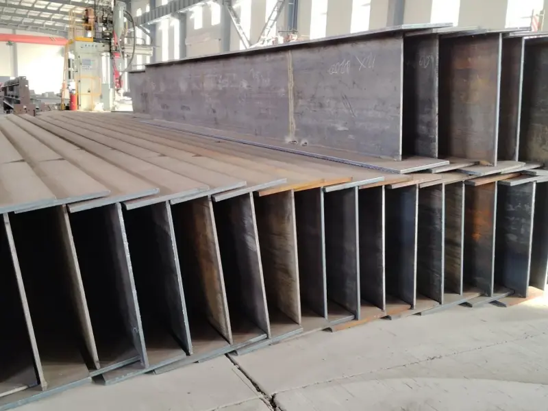
A capping beam is not just a cosmetic detail
I often see people treat the capping beam as a finishing item. In many projects, that is too simple. A capping beam can be structural, geometric, and practical at the same time.
At the most basic level, a capping beam gives the top of the wall a clean line. It also helps connect slightly uneven pile heads into one continuous edge. That matters on exposed waterfront walls, urban retaining walls, and bridge approaches where appearance and dimensional control are important.
But the bigger reason is load transfer. In some projects, the top of the wall must support parapets, barriers, deck loads, crane rails, or local slab reactions. In those cases, the capping beam is not optional decoration. It becomes part of the structural system.
When I usually recommend a capping beam
I tend to recommend a capping beam in the following situations:
1. Permanent exposed retaining walls
If the wall will remain visible and accessible for years, a capping beam improves top-line accuracy and protects the pile heads.
2. Marine walls with accessories or superstructure loads
If bollards, fenders, handrails, deck elements, or other loads connect to the top of the wall, the capping beam helps distribute these forces.
3. Bridge abutments and integrated support systems
Where vertical and horizontal loads need to be transferred into the sheet pile wall, a reinforced capping beam can be a key connection element.
4. Urban walls with strict finish requirements
In city projects, the top of wall often needs a neat finish for safety barriers, paving, drainage details, or pedestrian areas.
When a wall may work without a capping beam
Some temporary excavation walls do not need one. A simple temporary shoring wall may be cut off below final grade or removed after use. In that case, the wall may perform well without a capping beam if there is no need for top restraint, top finish, or superstructure load transfer.
Some marine cut-off walls and low temporary retaining works also operate without a conventional cap, especially if the wall only serves as a buried barrier.
The design side: simple cap vs load-transferring cap
This is where I think many non-engineers miss the difference. Not all capping beams do the same job.
| Capping beam type | Main role | Typical use |
|---|---|---|
| Simple capping beam | Aligns and ties pile heads, improves finish | Permanent retaining walls with limited top loading |
| Structural load-transferring capping beam | Transfers vertical and horizontal loads into sheet piles | Bridge abutments, quay walls, integrated structural systems |
| Temporary top beam or wale arrangement | Helps construction bracing or alignment | Temporary excavations and staged works |
ArcelorMittal’s technical documents on knife-edge support and capping beam systems show that some reinforced concrete caps are designed specifically to transfer vertical and horizontal loads into steel sheet piles, and that detailing such as embedment length, cover, and reinforcement arrangement matters a lot.
My own view on capping beams
My own view is that a capping beam should be decided early, not after the sheet piles are already ordered. If the beam will carry real load, then it affects pile top detailing, tolerances, reinforcement, and even the pile section choice. If the beam is only for finishing, the detailing is easier. I prefer to settle that question before production, because once the steel is on site, changing the top connection detail is never cheap.
How to design pile reinforcement?
Steel sheet piles themselves are steel sections, so people often ask why reinforcement is even part of the discussion. The answer is that reinforcement usually belongs to the capping beam, wale zone, connection area, or composite system around the sheet pile wall.
Pile reinforcement in a steel sheet pile wall usually refers to reinforcing the concrete capping beam, load-transfer zone, or related structural elements rather than reinforcing the steel pile itself. The reinforcement design must follow the loads being transferred, the connection detail, crack control needs, cover requirements, and durability conditions.
First, I separate steel section design from reinforcement design
This is one of the most common points of confusion in sales discussions. A steel sheet pile wall already has a structural steel section. So when someone asks me about “pile reinforcement,” I first ask what they actually mean.
In most steel sheet pile projects, reinforcement does not mean putting rebar inside the steel pile. It usually means one of these four things:
- Reinforcement in the concrete capping beam at the top of the wall
- Reinforcement in a wale, coping, or load-transfer beam connected to the wall
- Reinforcement in a bridge or quay structure that uses the sheet pile wall as support
- Local strengthening details around anchors, connections, or embedded steel
Once I know which of these the client means, the design conversation becomes much clearer.
What I check when a capping beam must transfer load
If the capping beam is just a neat top finish, reinforcement demand may be modest. But if the capping beam transfers structural load into the sheet piles, then I look at it as a real reinforced concrete design problem.
1. Vertical loads
These may come from parapets, deck slabs, bridge elements, traffic barriers, or superimposed permanent loads.
2. Horizontal loads
These may come from impact, braking, soil surcharge reactions, handrail loading, or deck restraint.
3. Eccentricity of load
If the load is not centered on the sheet pile wall axis, torsion and extra bending can appear in the cap.
4. Local bearing and anchorage
The connection between concrete and steel must be detailed so the force can enter the sheet pile wall safely.
5. Crack control and durability
Marine or splash-zone work needs special attention to concrete cover, exposure class, and reinforcement detailing.
A simple design workflow I use in conversations
| Step | What I review | Why it matters |
|---|---|---|
| Define loads | Vertical, horizontal, accidental, service loads | Reinforcement amount depends on real load path |
| Define support condition | Simple cap or fixed/load-transferring cap | Changes bending and shear behavior |
| Check geometry | Cap width, height, pile spacing, embedment into cap | Controls load spread and bar arrangement |
| Design reinforcement | Longitudinal bars, stirrups, local anchorage bars | Resists bending, shear, and crack opening |
| Check durability | Cover, concrete grade, exposure class | Controls long-term service performance |
ArcelorMittal’s capping beam and underground car park guidance shows that reinforced concrete capping beams can be designed to transfer high vertical and horizontal loads into steel sheet piles, and that the geometry and reinforcement are part of a validated design approach in some applications.
Reinforcement also matters at transitions and details
In my experience, problems do not always come from the main beam span. They often come from the ends, corners, anchor zones, or changes in wall geometry. A straight wall with a simple top cap is one thing. A corner near a gate opening, a bridge seat, or a service duct is another. Those local details can drive reinforcement congestion, cracking risk, and construction difficulty.
That is why I prefer to review the drawing set as a whole. I want to know where the wall starts and ends, whether the cap changes elevation, whether anchors connect near the top, and whether utilities pass through the beam zone.
My own view on “reinforcement” in sheet pile projects
My own view is that reinforcement should be treated as part of the connection design, not as an afterthought. In a B2B supply discussion, the steel sheet pile and the capping beam are often handled by different teams. One team talks about section modulus and coating. The other talks about rebar and concrete cover. But the wall only performs well if those two teams are working from the same load path. I have learned that when I ask better questions about the cap and connection, I can avoid many late-stage design changes.
What is the life of sheet pile wall design?
A sheet pile wall is not designed for one universal lifespan. Design life depends on the project type, environment, corrosion risk, maintenance plan, and owner expectations.
The design life of a steel sheet pile wall is often set at 25, 50, 75, or even 100 years depending on whether the wall is temporary or permanent, and on how corrosion is managed. In many permanent projects, service life is achieved by corrosion allowance, coatings, stronger sections, special steel grades, or cathodic protection.
I always ask this question early: temporary wall or permanent wall?
If the client says the wall is temporary, I think about short construction duration, removal method, and reuse potential. If the client says the wall is permanent, the design changes immediately. I start asking about groundwater chemistry, splash zone, marine exposure, access for inspection, and whether the owner expects a 50-year or 100-year service life.
A permanent wall is not just a temporary wall left in the ground. It is a different design problem.
What really controls sheet pile wall life?
1. Environment
Corrosion is usually the biggest factor for steel sheet pile design life. Natural inland soils can be relatively mild. Marine environments are much more aggressive, especially around splash, tidal, and low-water zones.
2. Section reserve or sacrificial thickness
One common design approach is to allow for expected steel loss over time and start with a thicker section.
3. Protective system
Coatings, cathodic protection, and corrosion-resistant grades can extend service life.
4. Stress location
If the highest bending stress is located in a zone with lower corrosion risk, the wall may perform better over time.
5. Maintenance and inspection access
A wall that can be inspected and repaired is easier to manage than a buried or inaccessible structure.
Typical design-life thinking I use in practice
| Project type | Typical design-life mindset | Main durability concern |
|---|---|---|
| Temporary excavation support | Short-term, often months to a few years | Damage during installation and extraction |
| Inland permanent retaining wall | 25–50+ years depending on owner criteria | Soil-side corrosion and drainage performance |
| Marine retaining wall or quay wall | 50–100 years in many major assets | Splash-zone and tidal corrosion |
| Bridge or infrastructure support wall | Long-term public asset design | Structural durability, inspection, and connection performance |
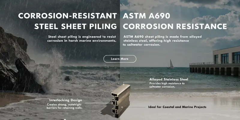
ArcelorMittal’s technical guidance notes that steel sheet piles are widely used in permanent earth-retaining and foundation works, and that the service life can be achieved by combining measures such as corrosion allowance, coatings, stronger sections, special grades like AMLoCor or ASTM A690 in suitable zones, and cathodic protection where needed. Their published durability tables based on EN 1993-5 also show that steel thickness loss depends strongly on the environment and design lifetime.
My own rule: do not discuss design life without discussing corrosion zone
This is one of my strongest views. If someone asks, “How long will a sheet pile wall last?” and nobody asks where the wall is located, the answer is already weak. A riverbank wall in natural soil, a basement cut-off wall, and a tidal marine wall do not age in the same way. Even on one marine wall, the splash zone, immersion zone, and buried zone can behave differently.
I also think many buyers focus too much on initial steel tonnage and not enough on whole-life value. A slightly heavier section, a better steel grade in the right zone, or a planned protection system can reduce future repair risk. That does not mean every wall needs the most expensive protection. It means the design life target should be honest, and the durability strategy should match it.
Conclusion
I design a steel sheet pile wall by linking geotechnical stability, structural demand, top connection, and durability. If those four parts work together, the wall is far more likely to perform well for years.