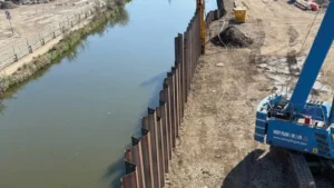
You are designing a new port terminal. The water is deep, the ships are large, and the soil is challenging. The sheet pile wall must hold back tons of soil while withstanding waves, berthing forces, and decades of corrosion.
Port sheet pile wall design requires careful consideration of embedment depth1, capping beams, pile formats, and corrosion protection. A well-designed wall balances structural stability, constructability, and long-term durability in the harsh marine environment.
](https://cnsteelplant.com/wp-content/uploads/2026/03/Article-Application-Port-1.webp)
I worked on a major port expansion in the Middle East where the design team spent months analyzing embedment depth1s and wall configurations. Getting it right was critical. The wall had to handle 50-foot container ships and survive for 50 years in seawater. Let me share what I learned from that project and others about designing port sheet pile walls.
What is the rule of thumb for sheet pile wall embedment1?
Embedment depth is one of the most critical decisions in sheet pile wall design. Get it wrong, and the wall can fail by rotating or pushing forward.
The general rule of thumb for sheet pile wall embedment1 in uniform soil is that the driven depth below the excavation or dredge line should be approximately equal to the exposed height of the wall. For cantilever walls2, embedment is typically 1 to 1.5 times the exposed height. For anchored walls3, embedment can be reduced to 0.5 to 0.8 times the exposed height.
[^1] depth relative to wall height](https://placehold.co/600x400 "Sheet Pile Wall Embedment Depth")](https://cnsteelplant.com/wp-content/uploads/2026/03/Article-Application-Port-3.webp)
Understanding Embedment Calculations
Let me explain the engineering behind these rules.
Cantilever Walls
Cantilever walls have no anchors or tiebacks. They rely entirely on the soil below the dredge line to hold them in place. These are used for moderate heights, typically up to 6 to 8 meters in good soil.
For cantilever walls2, the embedment depth (D) is roughly:
- D = H to 1.5H, where H is the exposed height
- In soft soil, you need more embedment
- In dense soil or rock, you may need less
The wall rotates around a point near the bottom. The passive soil resistance below must balance the active soil pressure above. This is a classic geotechnical calculation.
Anchored Walls
For taller walls, anchors or tiebacks are added. These reduce the bending moment in the wall and allow shallower embedment.
For anchored walls3, the embedment depth is roughly:
- D = 0.5H to 0.8H
- The anchor provides additional restraint, so less embedment is needed
- The embedment must still be sufficient to prevent bottom kick-out
Factors That Change Embedment
The rule of thumb is a starting point. Actual embedment depends on:
- Soil type: Sandy soils provide better passive resistance than clays
- Water level: Water on the excavated side reduces effective stress
- Wall height: Taller walls need proportionally deeper embedment
- Anchor location: Deeper anchors allow shallower embedment
- Safety factors: Permanent structures use higher factors than temporary
Real Example from Port Design
For the Middle East port project, the wall height was 18 meters. The soil was dense sand. The engineer calculated embedment of 9 meters for the anchored wall—exactly 0.5H. The rule of thumb was a good starting point, but the final design required detailed analysis of soil properties and anchor locations.
When Rules of Thumb Fail
Rules of thumb are useful for preliminary estimates, but they can fail in:
- Very soft clay, where passive resistance is low
- Layered soils with weak layers
- High water pressure conditions
- Seismic zones
Always verify with proper geotechnical analysis4 before finalizing design.
Do sheet piles need a capping beam1?
You see capping beam1s on many sheet pile walls. Are they always necessary?
Sheet piles do not always need a capping beam1, but they are highly recommended for most permanent walls. A capping beam1 distributes loads from the structure above, provides lateral restraint to the top of the piles, protects the pile tops from corrosion and impact, and creates a finished, accessible edge. For anchored walls, the anchor connections are often integrated into the capping beam1.
[^1] on top of sheet pile wall](https://placehold.co/600x400 "Sheet Pile Capping Beam")](https://cnsteelplant.com/wp-content/uploads/2026/03/Article-Application-Port-3-1.webp)
Functions of a Capping Beam
Let me explain why capping beam1s are so common.
Structural Functions
A capping beam1 serves several structural purposes2:
- Distributes concentrated loads: If a crane or other equipment sits on the wall, the beam spreads the load across multiple piles
- Provides lateral restraint: The top of the piles is fixed in position, which reduces bending moments
- Integrates anchor connections: Tie rods or ground anchors often connect to the capping beam1, not directly to the piles
- Creates a rigid header: The beam connects all piles into a single structural unit
Durability Functions
The marine environment is hard on steel. A capping beam1:
- Protects pile tops from corrosion: The steel extends into the concrete, which provides a barrier
- Prevents impact damage: Ships and equipment can hit the wall top; concrete protects the steel
- Provides a sacrificial element: Concrete can be repaired; steel corrosion is harder to fix
Operational Functions
A capping beam1 also makes the wall usable:
- Creates a walking surface: The top of the wall becomes a deck
- Provides attachment points: Bollards, fenders, railings mount to the beam
- Establishes a finished edge: The wall looks complete and professional
When You Might Skip a Capping Beam
There are situations where a capping beam1 is not required:
- Temporary walls: Excavation support that will be removed
- Very low walls: Under 2 meters, where the loads are minimal
- Special designs: Some walls use steel walers instead of concrete beams
- Cost constraints: The added cost may not be justified for non-critical applications
Design Considerations
If you use a capping beam1, consider:
- Width: Must accommodate pile width plus cover
- Reinforcement: Must handle the applied loads
- Connection to piles: Welded studs or embedded extensions
- Drainage: Weep holes to prevent water buildup
- Expansion joints: For long walls, allow for movement
My Experience
For the port project in the Middle East, we designed a massive concrete capping beam1. It was 1.2 meters wide and 0.8 meters deep, with the sheet piles embedded 0.5 meters into it. The beam distributed the berthing loads from ships and provided a flat deck for mooring operations. Without it, the wall would have had exposed steel tops that would corrode quickly and would not have handled the impact loads.
What are the 4 formats of pile foundation?
When you design a port structure, you may use different types of piles for different functions. Understanding the formats helps you choose.
The four main formats of pile foundations are end-bearing piles, friction piles, combination piles, and sheet piles. For port structures1, you often use all four in different parts of the facility.
](https://cnsteelplant.com/wp-content/uploads/2026/03/Article-Application-Port-2.webp)
Detailed Explanation of Each Format
Let me explain each format and how it applies to port design.
1. End-Bearing Piles2
End-bearing piles transfer load through weak soil to a strong bearing layer below. The pile acts like a column standing on bedrock or very dense soil.
- How they work: The bottom of the pile bears on a hard layer
- Typical materials: Concrete, steel H-piles, pipe piles
- Port applications: Bridge piers, heavy crane foundations, major structures
- Driving: Must reach the bearing layer, often requiring hard driving
2. Friction Piles3
Friction piles transfer load through skin friction along the pile shaft. The soil grips the pile and holds it up.
- How they work: The load is transferred through friction between pile and soil
- Typical materials: Steel pipe, concrete, timber
- Port applications: Wharf decks, lighter structures, areas with deep soft soil
- Driving: Depth determined by required friction capacity, not bearing layer
3. Combination Piles4
Combination piles use both end-bearing and friction to carry loads. This is common when piles are driven through soft soil to a bearing layer but also develop significant friction along the way.
- How they work: Part of the load goes to the tip, part to the shaft
- Typical materials: Steel pipe, concrete
- Port applications: Most deep foundations combine both mechanisms
- Driving: Piles are driven to a specified depth or resistance
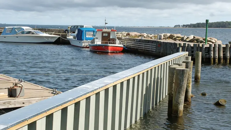
4. Sheet Piles5
Sheet piles are retaining walls, not load-bearing piles. They hold back soil and water but do not support vertical loads from structures.
- How they work: Interlocked sections form a continuous wall that resists lateral pressure
- Typical materials: Steel (U, Z, straight web)
- Port applications: Quay walls, bulkheads, cofferdams, seawalls
- Driving: Driven to achieve required embedment for stability
How Formats Work Together in a Port
A typical port uses multiple formats:
- Sheet piles form the quay wall that holds back the land
- End-bearing piles support heavy crane rails at the dock edge
- Friction piles support the wharf deck behind the wall
- Combination piles may support the main structural elements
The sheet pile wall is the first line of defense, holding back soil and water so the other piles can be installed and the deck can be built.
My Experience
For the Middle East port, the sheet piles were the primary quay wall. Behind them, we installed friction piles for the deck structure. At the crane rail, we used end-bearing piles driven to rock. Each format served its purpose.
What are the disadvantages of using sheet piles?
Sheet piles are excellent for port walls, but they have limitations. You need to know them before you design.
The main disadvantages of sheet piles are corrosion in marine environments1, difficulty driving in hard soils2 or through obstructions, potential for interlock failure3 if not installed plumb, noise and vibration during installation4, limited height for cantilever walls without anchors, and higher initial cost compared to some alternatives like timber.
](https://cnsteelplant.com/wp-content/uploads/2026/03/Article-Application-Port-4.webp)
Addressing the Disadvantages
Let me discuss each disadvantage and how engineers address it.
Corrosion
Seawater is corrosive. Steel sheet piles will corrode over time.
- Mitigation: Use marine grade steel (ASTM A690), cathodic protection, coatings, or add corrosion allowance (extra thickness)
- Design approach: Calculate expected corrosion rate over design life, specify appropriate protection
- For permanent port walls, cathodic protection plus marine grade is common
Driving Difficulties
Hard soils, boulders, and rock layers can make driving difficult or impossible.
- Mitigation: Pre-drilling, jetting, impact hammers, or alternative foundation types
- Design approach: Geotechnical investigation must identify potential obstructions before design
- In some cases, sheet piles are not feasible and a different wall type is needed
Interlock Failure
If piles are not driven plumb, the interlocks can separate (declutch). This creates gaps in the wall.
- Mitigation: Use templates, guide frames, experienced crews, and pile gates
- Design approach: Specify tolerances for plumbness and alignment
- For critical walls, consider Z piles with ball-and-socket interlocks that are more forgiving
Noise and Vibration
Pile driving is loud and creates vibration that can affect nearby structures.
- Mitigation: Vibratory hammers (quieter), press-in methods (almost silent), pre-augering
- Design approach: Consider site constraints during planning, plan for noise mitigation
- Urban port sites may have strict noise limits that require silent methods
Height Limitations
Cantilever sheet pile walls are limited to about 6 to 8 meters in good soil.
- Mitigation: Add anchors or tiebacks for taller walls
- Design approach: For port walls, anchored walls are standard for heights over 5 meters
- Anchored walls can reach 20 meters or more with proper design
Cost
Steel sheet piles have higher initial cost than timber or some concrete alternatives.
- Mitigation: Consider lifecycle cost, not just initial cost. Steel lasts longer, requires less maintenance, and can be reused
- Design approach: For permanent port walls, the higher initial cost is justified by durability and reliability
- Compare total installed cost, including maintenance, over design life
Water Tightness
Sheet pile interlocks are not completely watertight without sealants.
- Mitigation: Use Larssen-type interlocks that tighten under soil pressure, or add sealants
- Design approach: For water control structures, specify sealants or accept some seepage
- For port walls, some seepage is usually acceptable; dewatering systems handle it
My Experience
For the Middle East port, we addressed these disadvantages head-on. We specified A690 marine grade steel for corrosion resistance. We used a heavy impact hammer with pre-drilling to penetrate the dense sand. We required the contractor to use guide frames to maintain alignment. The wall was anchored at two levels to handle the 18-meter height. The design anticipated the challenges and built in solutions.
Conclusion
Port sheet pile wall design requires careful attention to embedment depth1, capping beams, pile formats, and corrosion protection2. Address the disadvantages with proven mitigation strategies for long-term success.
-
Understanding embedment depth is crucial for ensuring the stability and longevity of sheet pile walls in marine environments. ↩ ↩ ↩ ↩ ↩ ↩ ↩ ↩ ↩ ↩ ↩ ↩ ↩ ↩ ↩ ↩ ↩ ↩ ↩ ↩
-
Exploring corrosion protection methods can help you enhance the durability and performance of your sheet pile structures. ↩ ↩ ↩ ↩ ↩ ↩
-
Learn about interlock failure causes and prevention methods to ensure the integrity of sheet pile walls. ↩ ↩ ↩ ↩
-
Discover innovative techniques to minimize noise and vibration, ensuring compliance with urban regulations. ↩ ↩ ↩
-
Find out how Sheet Piles function as retaining walls and their importance in port and waterfront construction. ↩